Tay Bridge disaster
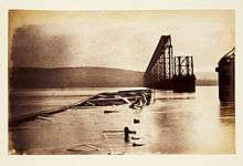
 Contemporary illustration of the search after the disaster | |
| Date | 28 December 1879 |
|---|---|
| Time | 7:16 pm |
| Location | Dundee |
| Country | Scotland |
| Rail line | Edinburgh to Aberdeen Line |
| Operator | North British Railway |
| Cause | Structural failure |
| Statistics | |
| Trains | 1 |
| Passengers | 70 |
| Deaths | 75 estimate, 60 known dead |
| Injuries | 0 |
| List of UK rail accidents by year | |
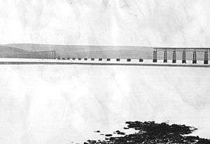
The Tay Bridge disaster occurred during a violent storm on 28 December 1879 when the first Tay Rail Bridge collapsed while a train was passing over it from Wormit to Dundee, killing all aboard. The bridge—designed by Sir Thomas Bouch—used lattice girders supported by iron piers, with cast iron columns and wrought iron cross-bracing. The piers were narrower and their cross-bracing was less extensive and robust than on previous similar designs by Bouch.
Bouch had sought expert advice on "wind loading" when designing a proposed rail bridge over the Firth of Forth; as a result of that advice he had made no explicit allowance for wind loading in the design of the Tay Bridge. There were other flaws in detailed design, in maintenance, and in quality control of castings, all of which were, at least in part, Bouch's responsibility.
Bouch died within the year, with his reputation as an engineer ruined. Future British bridge designs had to allow for wind loadings of up to 56 pounds per square foot (2.7 kPa). Bouch's design for the Forth Bridge was not used.
The bridge

Construction began in 1871 of a bridge to be supported by brick piers resting on bedrock. Trial borings had shown the bedrock to lie at no great depth under the river. At either end of the bridge, the bridge girders were deck trusses, the tops of which were level with the pier tops, with the single track railway running on top. However, in the centre section of the bridge (the "high girders") the bridge girders ran as through trusses above the pier tops (with the railway inside them) in order to give the required clearance to allow passage of sailing ships to Perth.[1]
The bedrock actually lay much deeper than the trial borings had shown, and Bouch had to redesign the bridge, with fewer piers and correspondingly longer span girders. The pier foundations were now constructed by sinking brick-lined wrought-iron caissons onto the riverbed, and filling these with concrete. To reduce the weight these had to support, Bouch used open-lattice iron skeleton piers: each pier had multiple cast-iron columns taking the weight of the bridging girders. Wrought iron horizontal braces and diagonal tiebars linked the columns in each pier to provide rigidity and stability. The basic concept was well known, but for the Tay Bridge, the pier dimensions were constrained by the caisson. For the higher portion of the bridge, there were 13 girder spans. In order to accommodate thermal expansion, at only 3 of their 14 piers was there a fixed connection from the pier to the girders. There were therefore 3 divisions of linked high girder spans, the spans in each division being structurally connected to each other, but not to neighbouring spans in other divisions.[2] The southern and central divisions were nearly level, but the northern division descended towards Dundee at gradients of up to 1 in 73.[3]
The bridge was built by Hopkin Gilkes and Company, a Middlesbrough company which had worked previously with Bouch on iron viaducts. Gilkes, having first intended to produce all ironwork on Teesside, used a foundry at Wormit to produce the cast-iron components, and to carry out limited post-casting machining. Gilkes were in some financial difficulty; they ceased trading in 1880, but had begun liquidation in May 1879, before the disaster.[4] Bouch's brother had been a director of Gilkes,[note 1] and on his death in January 1876, Bouch had inherited Gilkes shares valued at £35,000 but also owed for a guarantee of £100,000 of Gilkes borrowings and been unable to extricate himself.[5]
The change in design increased cost and necessitated delay, intensified after two of the high girders fell when being lifted into place in February 1877. However, the first engine crossed the bridge in September, 1877. A Board of Trade inspection was conducted over three days of good weather in February 1878; the bridge was passed for use by passenger traffic. However, it was subjected to a 25 mph speed limit, and the inspection report noted:
When again visiting the spot I should wish, if possible, to have an opportunity of observing the effects of high wind when a train of carriages is running over the bridge.[6]
The bridge was opened for passenger services on 1 June 1878. Bouch was knighted in June 1879 soon after Queen Victoria had used the bridge.
The disaster
On the evening of 28 December 1879, a violent storm (10 to 11 on the Beaufort scale) was blowing virtually at right angles to the bridge.[7] Witnesses said the storm was as bad as any they had seen in the 20–30 years they had lived in the area;[8][9] one called it a 'hurricane',[note 2] as bad as a typhoon he had seen in the China Sea.[10] The wind speed was measured at Glasgow – 71 mph (114 km/h) (averaged over an hour) – and Aberdeen, but not at Dundee. Higher windspeeds were recorded over shorter intervals, but at the inquiry an expert witness warned of their unreliability, and declined to estimate conditions at Dundee from readings taken elsewhere.[11] One modern interpretation of available information suggests winds were gusting to 80 mph (129 km/h).[12]
Usage of the bridge was restricted to one train at a time by a signalling block system using a baton as a token. At 7:13 p.m. a train from the south (consisting of a 4-4-0 locomotive - its tender - a third class carriage - a first class carriage - a third class carriage - a third class carriage - a second class carriage - a luggage van (brake van),[13] slowed to pick up the baton from the signal cabin at the south end of the bridge, then headed out onto the bridge, picking up speed. The signalman turned away to log this and then tended the cabin fire, but a friend present in the cabin watched the train: when it got about 200 yards (183 m) from the cabin he saw sparks flying from the wheels on the east side,[note 3] this continued for no more than three minutes, by then the train was in the high girders;[15] then "there was a sudden bright flash of light, and in an instant there was total darkness, the tail lamps of the train, the sparks and the flash of light all ... disappearing at the same instant."[16] The signalman saw none of this and did not believe when told about it.[note 4] When the train failed to appear on the line off the bridge into Dundee he tried to talk to the signal cabin at the north end of the bridge, but found that all communication with it had been lost.[17]
Not only was the train in the river, but so were the high girders, and much of the ironwork of their supporting piers.[18] Divers exploring the wreckage later found the train still within the girders, with the engine in the fifth span of the southern 5-span division.[19] There were no survivors; only 46 bodies were recovered [20] but there were 59 known victims. Fifty-six tickets for Dundee had been collected from passengers on the train before crossing the bridge; allowing for season ticket holders, tickets for other destinations, and for railway employees, 74 or 75 people were believed to have been on the train.[16] [note 5]
Court of Inquiry – evidence
A Court of Inquiry (a judicial enquiry under Section 7 of the Regulation of Railways Act 1871 'into the causes of, and circumstances attending' the accident) was immediately set up: Henry Cadogan Rothery, Commissioner of Wrecks, presided, supported by Colonel Yolland (Inspector of Railways) and William Henry Barlow, President of the Institution of Civil Engineers. By 3 January 1880, they were taking evidence in Dundee; they then appointed Henry Law (a qualified civil engineer) to undertake detailed investigations. Whilst awaiting his report they held further hearings in Dundee (26 February – 3 March); having got it they sat at Westminster (19 April – 8 May) to consider the engineering aspects of the collapse.[22] By then railway, contractor and designer had separate legal representation, and the NBR had sought independent advice (from James Brunlees and John Cochrane[note 6], both engineers with extensive experience of major cast-iron structures). The terms of reference did not specify the underlying purpose of the inquiry – to prevent a repetition, to allocate blame, to apportion liability or culpability, or to establish what precisely had happened. This led to difficulties (culminating in clashes) during the Westminster sessions and when the court reported their findings at the end of June, there was both an Inquiry Report signed by Barlow and Yolland and a minority report by Rothery.
Other eyewitnesses
Two witnesses, viewing the high girders from the north almost end-on, had seen the lights of the train as far as the 3rd–4th high girder, when they disappeared; this was followed by three flashes from the high girders north of the train. One witness said these advanced to the north end of the high girders with about 15 seconds between first and last;[24][note 7] the other that they were all at the north end, with less time between.[25] A third witness had seen 'a mass of fire fall from the bridge' at the north end of the high girders.[26] A fourth said he had seen a girder fall into the river at the north end of the high girders, then a light had briefly appeared in the southern high girders, disappearing when another girder fell; he made no mention of fire or flashes.[27][note 8] 'Ex-Provost' Robertson[note 9] had a good view of most of the bridge from his house in Newport-on-Tay[note 10] but other buildings blocked his view of the southern high girders. He had seen the train move onto the bridge; then in the northern high girders, before the train could have reached them, he saw two columns of spray illuminated with the light, first one flash and then another and could no longer see the lights on the bridge[note 11] – the only inference he could draw was that the lit columns of spray – slanting from north to south at about 75 degrees – were areas of spray lit up by the bridge lights as it turned over.[32]
How the bridge was used – speed of trains and oscillation of bridge
Ex-Provost Robertson had bought a season ticket between Dundee and Newport at the start of November, and became concerned about the speed of north-bound local trains through the high girders, which had been causing perceptible vibration, both vertical and lateral. After complaining on three occasions to the stationmaster at Dundee, with no effect on train speed, after mid-December he had used his season ticket to travel south only, using the ferry for north-bound crossings.
Robertson had timed the train with his pocket watch, and to give the railway the benefit of the doubt he had rounded up to the nearest 5 seconds. The measured time through the girders (3,149 ft (960 m)) was normally 65 or 60 seconds,[note 12] but twice it had been 50 seconds. When observing from the shore, he had measured 80 seconds for trains travelling through the girders, but not on any train he had travelled on. North-bound local trains were often held up to avoid delaying expresses, and then made up time while travelling over the bridge. The gradient onto the bridge at the northern end prevented similar high speeds on south-bound locals. Robertson said that the movement he observed was hard to quantify, although the lateral movement, which was probably one or two inches (25 to 50 mm), was definitely due to the bridge, not the train, and the effect was more marked at high speed.
Four other train passengers supported Robertson's timings but only one had noticed any movement of the bridge.[34][note 13] The Dundee stationmaster had passed Robertson's complaint about speed (he had been unaware of any concern about oscillation) on to the drivers, and then checked times from cabin to cabin (at either end of the bridge the train was travelling slowly to pick up or hand over the baton). However he had never checked speed through the high girders.[36]
Painters who had worked on the bridge in mid-1879 said that it shook when a train was on it.[37][note 14] When a train entered the southern high girders the bridge had shaken at the north end, both east-west and, more strongly, up-and-down.[40] The shaking was worse when trains were going faster, which they did: 'when the Fife boat was nearly over and the train had only got to the south end of the bridge it was a hard drive'.[41] A joiner who had worked on the bridge from May to October 1879 also spoke of a lateral shaking, which was more alarming than the up-and-down motion, and greatest at the southern junction between the high girders and the low girders. He was unwilling to quantify the amplitude of motion, but when pressed he offered 2 to 3 inches (50 to 75 mm). When pressed further he would only say that it was distinct, large, and visible.[42] One of the painters' foremen, however, said the only motion he had seen had been north-south, and that this had been less than half an inch (12 mm).[43]
How the bridge was maintained – chattering ties and cracked columns
The North British Railway maintained the tracks, but it retained Bouch to supervise maintenance of the bridge. He appointed Henry Noble as his bridge inspector.[44] Noble, who was a bricklayer, not an engineer, had worked for Bouch on the construction of the bridge.[45]
Whilst checking the pier foundations to see if the river bed was being scoured from around them, Noble had become aware that some diagonal tie bars were 'chattering',[note 15] and in October 1878 had begun remedying this. Diagonal bracing was by flat bars running from one lug at a column section top to two sling plates bolted to a lug at the base of the equivalent section on an adjacent column. The bar and sling plates all had a matching longitudinal slot in them. The tie bar was placed between the sling plates with all three slots aligned and overlapping, and then a gib was driven through all three slots and secured. Two "cotters" (metal wedges)[note 16] were then positioned to fill the rest of the slot overlap, and driven in hard to put the tie under tension.
Noble had assumed the cotters were too small and had not been driven up hard in the first place, but on the chattering ties the cotters were loose, and even if driven fully in would not fill the slot and put the bar under tension. By fitting an additional packing piece between loose cotters and driving the cotters in, Noble had re-tightened loose ties and stopped them chattering. There were over 4,000 gib and cotter joints on the bridge, but Noble said that only about 100 had had to be re-tensioned, most in October–November 1878. On his last check in December 1879, only two ties had needed attention, both on piers north of the high girders. Noble had found cracks in four column sections – one under the high girders, three to the north of them – which had then been bound with wrought iron hoops. Noble had consulted Bouch about the cracked columns, but not the chattering ties.[47]
How the bridge was built – The Wormit Foundry
The workers at the Wormit foundry complained that the columns had been cast using 'Cleveland iron', which always had scum on it: it was less easy to cast than 'good Scotch metal'[48][note 17] and more likely to give defective castings. Moulds were damped with salt water,[49] cores were inadequately fastened, and moved, giving uneven column wall thickness.[50] The foundry foreman explained that where lugs had been imperfectly cast, the missing metal was added by 'burning on';[note 18] blowholes and other casting defects in the column if minor faults had been filled with 'Beaumont egg'[note 19] which he kept a stock of for that purpose and the casting used.[52]
How the bridge was built – management and inspection
Gilkes' site staff were inherited from the previous contractor. Under the resident engineer there were seven subordinates including a foundry manager. The original foundry manager left before most of the high girders pier column sections were cast; his replacement was also supervising erection of the bridge, and had no previous experience of supervising foundry work.[53] He was aware of 'burning on',[54] but the use of Beaumont egg had been hidden from him by the foreman;[55] when shown defects in bridge castings he said he would not have passed the affected column for use; nor would he have passed columns with noticeably uneven wall thickness.[53] According to his predecessor, burning on had only been carried out on temporary 'lifting columns' used to lift girders into place and not part of the permanent bridge structure;[56] this was on the instructions of the resident engineer[57] who had little foundry experience either, and relied upon the foreman.[58]
Whilst the working practices were the responsibility of Gilkes, their contract with NBR provided that all work done by the contractor was subject to approval of workmanship by Bouch; hence Bouch would share the blame for any resulting defective work being present in the finished bridge. The original foundry foreman (dismissed for drunkenness) vouched for Gilkes personally testing for unevenness in the early castings; "Mr.Gilkes, sometimes once a fortnight and sometimes once a month, would tap a column with a hammer, first on one side and then on the other, and he used to go over most of them in that way sounding them.":[59] Bouch had spent over £9,000 on inspection (his total fee was £10,500[60]) but produced no witness who had inspected castings on his behalf. Bouch himself had been up about once a week whilst the design was being changed, but 'afterwards, when it was all going on, I did not go so often'.[61] He had his own 'resident engineer' (William Paterson) who looked after construction of the bridge, its approaches, the line to Leuchars and the Newport branch and was also the engineer of the Perth General Station.[61]- Bouch told the court Paterson's age was 'very much mine', but actually Paterson was 12 years older[note 20] and by the time of the Inquiry paralysed and unable to give evidence.[63] Another inspector appointed later[63] was now in South Australia and also unable to give evidence. Gilkes' managers did not vouch for any inspection of castings by Bouch's inspectors[64] The completed bridge had been inspected on behalf of Bouch for quality of assembly, but after the bridge was painted[note 21] which would have hidden cracks or signs of burning on (which the inspector said he would not know if he saw).[65] Throughout Mr Noble had been looking after foundations and brickwork.[note 22]
"The evidence of the ruins"
Henry Law had examined the remains of the bridge; he reported defects in workmanship and design detail. Cochrane and Brunlees, who gave evidence later, largely concurred.
- The piers had not shifted or settled, but the masonry of the pier bases showed poor adhesion between stone and cement (the stone had been left too smooth, and had not been wetted before adding the cement). The hold-down bolts to which the column bases were fastened were poorly designed, and burst through the masonry too easily.[67]
- The connecting flanges on column sections were not fully faced[note 23]; the spigot which should have given positive location of one section in the next was not always present[note 24], and the bolts did not fill the holes. Consequently, the only thing resisting one flange sliding over another was the pinching-down action of the bolts.[69] This was reduced as boltheads and nuts were unfaced – some nuts had burrs up to 0.05 inch on them (he produced an example). This prevented any holding-down power, and if such a nut was used at a column base joint and the burr subsequently crushed, there would be over 2 inches free play at the top of the column. The nuts used were abnormally short and thin.[70]
- The column bodies were of uneven wall thickness, as much as ½ inch out; sometimes because the core had shifted, sometimes because the two halves of the mould were misaligned. Thin metal was undesirable, both in itself and because (since it cooled quicker) it would be more vulnerable to 'cold shuts'
Here (producing a specimen) is a nodule of cold metal which has been formed. The metal, as one would expect in the thin part, is very imperfect. Here is a flaw which extends through the thickness of the metal. Here is another and here is another...It will be found that all the upper side of this column is of that description, perfectly full of air-holes and cinders. There are sufficient pieces here to show that these flaws were very extensive.[71]
Bouch said uneven thickness was unworkmanlike – if he had known he would have taken the best means to cast vertically – but safe.[72] - The channel-iron horizontal braces did not butt up against the column body – correct separation was dependent on bolts being tightly nipped up; previous comments about lack of facing applied here also. Because holes in lugs were cast not drilled, their position was more approximate, and some horizontal braces had been site-fitted, leaving burrs up to 3/16th inch.[71]
- In the diagonal bracing; the gib and cotters were roughly forged and left unfaced, and were much too small to withstand in compression the force the bracing bars could put on them.[note 25]
- On the southernmost fallen pier, every tie bar to the base of one of the columns had had a packing piece fitted .[73]
- The bolt holes for the lugs were cast with a taper; consequently the bolt-lug contact was by the bolt thread bearing against a knife edge at the outer end of the hole. The thread would easily crush and allow play to develop, and the off-centre loading would fail the lugs at much lower loads than if the hole was cylindrical.[74] Cochrane added that the bolt would bend permanently (and slacken its tiebar to about the extent that had had to be taken up by packing pieces) at an even lower loading than the cotters would deform; he had found some bent tiebar bolts.[75]
- The bracing had failed by the lugs giving way; in nearly every case, the fracture ran through the hole. Law had seen no evidence of 'burnt-on' lugs[74] but some lug failures were by lug and a surrounding area of column breaking away from the rest of the column (what would be expected where burning-on had taken place) and on intact columns paint would hide any evidence of burning-on.[76]
- At some piers, base column sections were still standing; at others base sections had fallen to the west;[77] Cochrane added that fallen girders lay on top of the eastern columns, but the western columns on top of the girders; hence the engineers[77][78][79] concurred that the bridge had broken up before it fell, not as a consequence of it toppling.
- From marks on the south end of the southernmost high girder, it had moved bodily eastwards for about 20 inches across the pier before falling to the north.[80]
Bridge materials
Samples of the bridge materials, both cast and wrought iron, were tested by David Kirkaldy, as were a number of bolts, tiebars, and associated lugs. Both the wrought and cast iron had good strength, while the bolts "were of sufficient strength and proper iron." [81][note 26] However, both ties and sound lugs failed at loadings of about 20 tons, well below what had been expected. Both ties[77] and lugs were weakened by high local stresses where the bolt bore on them.[74] Four of the fourteen lugs tested were unsound, having failed at lower than expected loadings. Some column top lugs outlasted the wrought iron, but the bottom lugs were significantly weaker.[82]
Court of Inquiry – opinions and analysis
Windloading
Windloading assumed in design
Bouch had designed the bridge, assisted in his calculations by Allan Stewart.[note 27] After the accident Stewart had assisted William Pole[note 28] in calculating what the bridge should have withstood.[note 29] On the authority of Stewart they had assumed that the bridge was designed against a wind loading of 20 pounds per square foot (psf) 'with the usual margin of safety'.[85][note 30] Bouch said that whilst 20 psf had been discussed, he had been 'guided by the report on the Forth Bridge' to assume 10 psf and therefore made no special allowance for wind loading.[87] He was referring to advice given by the Astronomer Royal, Sir George Biddell Airy in 1873 when consulted about Bouch's design for a suspension bridge across the Firth of Forth; that wind pressures as high as 40 psf might be encountered very locally, but averaged over a 1600 ft span 10 psf would be a reasonable allowance.[88] This advice had been endorsed by a number of eminent engineers.[note 31] Bouch also mentioned advice given by Yolland in 1869 – that the Board of Trade did not require any special allowance for wind loading for spans less than 200 ft, whilst noting this was for the design of girders not piers.[87][note 32]
Opinions on windloading allowance
Evidence was taken from scientists on the current state of knowledge on wind loading and from engineers on the allowance they made for it. Airy said that the advice given was specific to suspension bridges and the Forth; 40 psf could act over an entire span of the Tay Bridge and he would now advise designing to 120 psf i.e. 30 psf with the usual margin of safety.[88] The highest pressure measured at Greenwich was 50 psf; it would probably go higher in Scotland. Sir George Stokes agreed with Airy that ‘catspaws’, ripples on the water produced by gusts, could have a width of several hundred yards. Standard wind pressure measurements were of hydrostatic pressure which had to be corrected by a factor of 1.4–2 to give total wind loading – with a 60 mph wind this would be 12.5–18 psf.[90] Pole referred to Smeaton's work, where high winds were said to give 10 psf, with higher values being quoted for winds of 50 mph or above, with the caveat that these were less certain.[91] Brunlees had made no allowance for wind loading on the Solway viaduct because the spans were short and low – if he had had to, he would probably have designed against 30 psf with a safety margin of 4–5 (by limiting strength of iron).[86] Both Pole and Law had used a treatment from a book by Rankine.[note 33] Law gave Rankine's statement on the same page that the highest wind pressure seen in Britain was 55 psf as the reason for designing to 200 psf (i.e. 50 psf with a safety factor of 4); " in important structures, I think that the greatest possible margin should be taken. It does not do to speculate upon whether it is a fair estimate or not".[92] Pole had ignored it because no reference was given; he did not believe any engineer paid any attention to it when designing bridges;[93] he thought 20 psf a reasonable allowance; this was what Robert Stephenson had assumed for the Britannia Bridge. Benjamin Baker said he would design to 28 psf with a safety margin, but in 15 years of looking he had yet to see wind overthrow a structure that would withstand 20 psf. He doubted Rankine's pressures because he was not an experimentalist; told that the data were observations by the Regius Professor of Astronomy at Glasgow University [note 34]he doubted that the Professor had the equipment to take the readings.[94]
Baker's analysis
Baker argued that the wind pressure on the high girders had been no more than 15 psf, from the absence of damage to vulnerable features on buildings in Dundee and the signal cabins at the south end of the bridge. The Inquiry felt that these locations were significantly more sheltered, and therefore rejected this argument. Baker's subsequent work on wind pressures at the Forth Rail Bridge site[95] showed meteorologists were overestimating,[96] but his 15 psf might have over-interpreted the data.[note 35]
Opinions on bridge components
Law had numerous criticisms of the bridge design, some echoed by other engineers:
- He thought the piers should have been wider (both to counteract toppling and to increase the horizontal component forces the tiebars could withstand) and rectangular (to increase the number of tiebars directly resisting lateral forces); at the very least there should have been lateral bracing between the outermost columns of the piers.[99]
- The lug holes should have been drilled and the tiebars secured by pins filling the holes (rather than bolts)[70] (Cochrane had not been surprised that boltholes had been cast conical; moulders were notorious for this, unless you stood over them. Even so, he would not rely on supervision or inspection, he would have the holes bored or reamed to ensure they were cylindrical – it had an important bearing on the stability of the structure.[100] Pole – called by Bouch's counsel – agreed.[101] Bouch said if he had known the holes were cast conical he would have had them bored or reamed.[60] Gilkes said casting lug holes conical would have been done "as a matter of course, and unless attention had been drawn to it, it would not be thought then so important as we think it now".[102]
- Cast-on lugs tended to make unsound castings (Cochrane said he had seen examples in the bridge ruins[100]) and had prevented facing of the outer side of flanges.[99] Cochrane added that their use meant that columns had had to be cast horizontally rather than vertically, thus giving less satisfactory castings;[103] and unless lugs were carefully packed during bolting up they could be damaged or strained.[104] For so tall a pier Gilkes would have preferred some other means of attaching the ties to the columns "knowing how treacherous a thing cast iron is, but if an engineer gave me such a thing to make I should make it without question, believing that he had apportioned the strength properly".[102] A letter Bouch–Gilkes 22 January 1875 had noted that Gilkes was "inclined to prefer making the joints of the metal columns the same as on the Beelah and Deepdale".[105] Asked by Rothery why he had departed from the bracing arrangements on the Belah Viaduct, Bouch had referred to changed views on the force of the wind; pressed for other reasons he said Belah-style ties "were so much more expensive; this was a saving of money".[106]
Modelling of bridge failure and conclusions drawn
Both Pole and Law had calculated the wind loading needed to overturn the bridge to be over 30 psf (taking no credit for holding-down bolts fastening the windward columns to the pier masonry) [107] and concluded that a high wind should have overturned the bridge, rather than cause it to break up (Pole calculated the tension in the ties at 20 psf windloading to be more than the 'usual margin of safety' value of 5 tons per square inch but still only half the failure tension.[108]) Pole calculated the wind loading required to overturn the lightest carriage in the train (the second-class carriage) to be less than that needed to overturn the bridge; whereas Law – taking credit for more passengers in the carriage than Pole and for the high girders partially shielding carriages from the wind – had reached the opposite conclusion.[109]
Law: causes were windloading, poor design and poor quality control
Law concluded that the bridge as designed if perfect in execution would not have failed in the way seen[110](Cochrane went further; it 'would be standing now').[111] The calculations assumed the bridge to be largely as designed, with all components in their intended position, and the ties reasonably evenly loaded. If the bridge had failed at lower wind loadings, this was evidence that the defects in design and workmanship he had objected to had given uneven loadings, significantly reduced the bridge strength and invalidated the calculation.[109] Hence
I consider that in such a structure the thickness of the columns should have been determined, every individual column should have been examined, and not passed until it had received upon it the mark of the person who passed it as a guarantee that it had passed under his inspection ...I consider that every bolt should have been a steady pin, and should have fitted the holes to which it was applied, that every strut should have had a firm abutment, that the joints of the columns should have been incapable of movement, and that the parts should have been accurately fitted together, storey by storey upon land and carefully marked and put together again as they had been properly fitted.[109]
Pole: causes were windloading and impact of derailed carriages
Pole held that the calculation was valid; the defects were self-correcting or had little effect, and some other reason for the failure should be sought.[107] It was the cast iron lugs which had failed; cast iron was vulnerable to shock loadings, and the obvious reason for a shock loading on the lugs was one of the carriages being blown over and into a bridge girder.[107] Baker agreed, but held the wind pressure was not sufficient to blow over a carriage; derailment was either wind-assisted by a different mechanism or coincidental.[112] (Bouch's own view that collision damage to the girder was the sole cause of bridge collapse[113] found little support).
"Did the Train strike the Girders?"
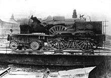 The locomotive was dropped during retrieval, but eventually recovered and returned to service.
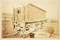 The left front of the recovered locomotive tender
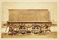 Right side of the recovered locomotive tender
 Two wagons holding wreckage salvaged from the train
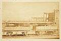 Opposite view of previous view showing two wagons holding salvaged wreckage
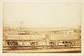 Salvaged wreckage from the train
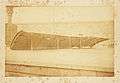 Salvaged wreckage from the train
Bouch's counsel called witnesses last; hence his first attempts to suggest derailment and collision were made piecemeal in cross-examination of universally unsympathetic expert witnesses. Law had 'not seen anything to indicate that the carriages left the line' (before the bridge collapse)[114] nor had Cochrane[78] nor Brunlees.[115] The physical evidence put to them for derailment and subsequent impact of one or more carriage with the girders was limited. It was suggested that the last two vehicles (the second-class carriage and a brake van) which appeared more damaged were those derailed, but (said Law) they were of less robust construction and the other carriages were not unscathed.[116] Cochrane and Brunlees added that both sides of the carriages were damaged very much alike.[111][117]
Bouch pointed to the rails and their chairs being smashed up in the girder holding the last 2 carriages, to the axle-box of the second-class carriage having become detached and ending up in the bottom boom of the eastern girder,[118] to the footboard on the east side of the carriage having been completely carried away, to the girders being broken up, and to marks on the girders showing contact with the carriage roof,[119] and to a plank with wheel marks on it having been washed up at Newport but unfortunately then washed away.[120] Bouch's assistant gave evidence of two sets of horizontal scrape marks (very slight scratches in the metal or paint on the girders) matching the heights of the roofs of the last two carriages, but did not know the heights he claimed to be matched.[121] At the start of one of these abrasions, a rivet head had lifted and splinters of wood were lodged between a tie bar and a cover plate. Evidence was then given of flange marks on tie bars in the fifth girder (north of the two rearmost carriages), the 'collision with girders' theory being duly modified to everything behind the tender having derailed.[118]
However, (it was countered) the girders would have been damaged by their fall regardless of its cause. They had had to be broken up with dynamite before they could be recovered from the bed of the Tay (but only after an unsuccessful attempt to lift the crucial girder in one piece which had broken many girder ties).[122] The tender coupling (which clearly could not have hit a girder) had also been found in the bottom boom of the eastern girder.[123] Two marked fifth girder tie bars were produced; one indeed had 3 marks, but two of them were on the underside.[124] Dugald Drummond, responsible for NBR rolling stock, had examined the wheel flanges and found no 'bruises' – expected if they had smashed up chairs. If the second-class carriage body had hit anything at speed, it would have been 'knocked all to spunks' without affecting the underframe.[note 36] Had collision with the eastern girder slewed the frame, it would have presented the east side to the oncoming brake van, but it was the west side of the frame that was more damaged. Its eastern footboard had not been carried away; the carriage had never had one (on either side). The graze marks were at 6–7 ft above the rail, and 11 ft above the rail and did not match carriage roof height.[126] Drummond did not think the carriages had left the rails until after the girders began to fall, nor had he ever known a carriage (light or heavy) to be blown over by the wind.[127]
Court of Inquiry findings


The three members of the court failed to agree a report although there was much common ground:[128]
Contributory factors
- neither the foundations nor the girders were at fault
- the quality of the wrought iron, whilst not of the best, was not a factor
- the cast iron was also fairly good, but presented difficulty in casting
- the workmanship and fitting of the piers was inferior in many respects
- the cross bracing of the piers and its fastenings were too weak to resist heavy gales. Rothery complained that the cross-bracing was not as substantial or as well-fitted as on the Belah viaduct;[129] Yolland and Barlow stated that the weight/cost of cross-bracing was a disproportionately small fraction of the total weight/cost of ironwork[130]
- there was insufficiently strict supervision of the Wormit foundry (a great apparent reduction of strength in the cast iron was attributable to the fastenings bringing the stress on the edges of the lugs, rather than acting fairly on them)[130]
- supervision of the bridge after completion was unsatisfactory; Noble had no experience of ironwork nor any definite instruction to report on the ironwork
- nonetheless Noble should have reported the loose ties.[note 37] Using packing pieces might have fixed the piers in a distorted form.
- the 25 mph limit had not been enforced, and frequently exceeded.
Rothery added that, given the importance to the bridge design of the test borings showing shallow bedrock, Bouch should have taken greater pains, and looked at the cores himself.[131]
"True Cause of the Fall of The Bridge"
According to Yolland and Barlow "the fall of the bridge was occasioned by the insufficiency of the cross-bracings and fastenings to sustain the force of the gale on the night of December 28th 1879 ... the bridge had been previously strained by other gales".[132] Rothery agreed, asking "Can there be any doubt that what caused the overthrow of the bridge was the pressure of the wind acting upon a structure badly built and badly maintained?"[131]
Substantive differences between reports
Yolland and Barlow also noted the possibility that failure was by fracture of a leeward column.[132] Rothery felt that previous straining was "partly by previous gales, partly by the great speed at which trains going north were permitted to run through the high girders":[131] if the momentum of a train at 25 mph hitting girders could cause the fall of the bridge, what must have been the cumulative effect of the repeated braking of trains from 40 mph at the north end of the bridge?[133] He therefore concluded – with (he claimed) the support of circumstantial evidence – that the bridge might well have failed at the north end first;[134] he explicitly dismissed the claim that the train had hit the girders before the bridge fell.[134]
Yolland and Barlow concluded that the bridge had failed at the south end first; and made no explicit finding as to whether the train had hit the girders.[132] They noted instead that apart from Bouch himself, Bouch's witnesses claimed/conceded that the bridge failure was due to a shock loading on lugs heavily stressed by windloading.[135] Their report is therefore consistent with either a view that the train had not hit the girder or one that a bridge with cross-bracing giving an adequate safety margin against windloading would have survived a train hitting the girder.
Yolland and Barlow noted "there is no requirement issued by the Board of Trade respecting wind pressure, and there does not appear to be any understood rule in the engineering profession regarding wind pressure in railway structures; and we therefore recommend the Board of Trade should take such steps as may be necessary for the establishment of rules for that purpose."[136] Rothery dissented, feeling that it was for the engineers themselves to arrive at an ‘understood rule’, such as the French rule of 55 psf or the US 50 psf.[137]
Presentational differences between reports
Rothery's minority report is more detailed in its analysis, more willing to blame named individuals, and more quotable, but the official report of the court is a relatively short one signed by Yolland and Barlow.[138] Rothery said that his colleagues had declined to join him in allocating blame, on the grounds that this was outside their terms of reference. However, previous Section 7 inquiries had clearly felt themselves free to blame (Thorpe rail accident) or exculpate (Shipton-on-Cherwell train crash) identifiable individuals as they saw fit, and when Bouch's solicitor checked with Yolland and Barlow, they denied that they agreed with Rothery that "For these defects both in the design, the construction, and the maintenance, Sir Thomas Bouch is, in our opinion, mainly to blame."[139]
Aftermath
Section 7 inquiries
No further judicial enquiries under Section 7 of the Regulation of Railways Act 1871 were held until the Hixon rail crash in 1968 brought into question both the policy of the Railway Inspectorate towards automated level crossings and the management by the Ministry of Transport (the Inspectorate's parent government department) of the movement of abnormal loads. A Section 7 judicial enquiry was felt necessary to give the required degree of independence.[140] The structure and terms of reference were better defined than for the Tay Bridge inquiry. Brian Gibbens, QC, was supported by two expert assessors, and made findings as to blame/responsibility but not as to liability/culpability.[141]
Wind Pressure (Railway Structures) Commission
The Board of Trade set up a 5-man commission (Barlow, Yolland, Sir John Hawkshaw, Sir William Armstrong and Stokes) to consider what wind loading should be assumed when designing railway bridges.
Windspeeds were normally measured in 'miles run in hour' (i.e. windspeed averaged over one hour) so it was difficult to apply Smeaton's table[142] which linked wind pressure to current windspeed

where:
- is the instantaneous wind pressure (pounds per square foot)
- is the instantaneous air velocity in miles per hour


By examination of recorded pressures and windspeeds at Bidston Observatory, the commission found[143] that for high winds the highest wind pressure could be represented very fairly,[note 38] by

where:
- is the maximum instantaneous wind pressure experienced (pounds per square foot)
- is the 'miles run in hour' (one hour average windspeed) in miles per hour


However, they recommended that structures should be designed to withstand a wind loading of 56 psf, with a safety factor of 4 (2 where only gravity was relied upon). They noted that higher wind pressures had been recorded at Bidston Observatory but these would still give loadings well within the recommended safety margins. The wind pressures reported at Bidston were probably anomalously high because of peculiarities of the site (one of the highest points on the Wirral.[145][146]): a wind pressure of 30–40 psf would overturn railway carriages and such events were a rarity. (To give a subsequent, well documented example, in 1903 a stationary train was overturned on the Levens viaduct but this was by a 'terrific gale' measured at Barrow in Furness to have an average velocity of 100 mph, estimated to be gusting up to 120 mph.[144])
Bridges
A new double-track Tay Bridge was built by the NBR, designed by Barlow and built by William Arrol & Co. of Glasgow 18 metres (59 ft) upstream of, and parallel to, the original bridge. Work started 6 July 1883 and the bridge opened on 13 July 1887. Sir John Fowler and Sir Benjamin Baker designed the Forth Rail Bridge, built (also by Arrols) between 1883 and 1890. Baker and his colleague Allan Stewart received the major credit for design and overseeing building work.[note 39] The Forth Bridge had a 40 mph speed limit, which was not well observed.[148]
Bouch had also been engineer for the North British, Arbroath and Montrose Railway, which included an iron viaduct over the South Esk. Examined closely after the Tay bridge collapse, the viaduct as built did not match the design, and many of the piers were noticeably out of the perpendicular. It was suspected that the construction had not been adequately supervised: foundation piles had not been driven deeply or firmly enough. After vigorous tests with stationary and rolling loads over a 36-hour period, the structure was seriously distorted. Condemning the structure, Colonel Yolland also stated his opinion that "piers constructed of cast-iron columns of the dimensions used in this viaduct should not in future be sanctioned by the Board of Trade."[149] Bouch's Redheugh Bridge built 1871 was condemned in 1896, the structural engineer doing so saying later that the bridge would have blown over if it had ever seen windloadings of 19 psf.[150]
Reminders

The locomotive, NBR no. 224, a 4-4-0 designed by Thomas Wheatley and built at Cowlairs Works in 1871, was salvaged and repaired, remaining in service until 1919, nicknamed "The Diver"; many superstitious drivers were reluctant to take it over the new bridge.[151][152][153][154] The stumps of the original bridge piers are still visible above the surface of the Tay. Memorials have been placed at either end of the bridge in Dundee and Wormit.[155]
Modern reinterpretations
Various additional pieces of evidence have been advanced in the last 40 years, leading to 'forensic engineering' reinterpretations of what actually happened.[156]
Works of literature about the disaster
| Wikisource has original text related to this article: |
Contemporary literature
The disaster inspired several songs and poems, most famously William McGonagall's The Tay Bridge Disaster, widely considered to be of such a low quality as to be comical.[157] Likewise, German poet Theodor Fontane, shocked by the news, wrote his poem Die Brück' am Tay. It was published only ten days after the tragedy happened. The ballad 'In Memory of the Tay Bridge Disaster' was published as a broadside in May 1880. It describes the moment of the disaster as:[158]
The train into the girders came,
And loud the wind did roar ;
A flash is seen-the Bridge is broke-
The train is heard no more.
"The Bridge is down, "the Bridge is down,"
in words of terror spread ;
The train is gone, its living freight
Are numbered with the dead.
Subsequent literature
Hatter's Castle, the 1931 novel of Scottish author A. J. Cronin, includes a scene involving the Tay Bridge Disaster, and the 1942 filmed version of the book dramatically recreates the bridge's catastrophic collapse. The events of Alanna Knight's 1976 novel A Drink for the Bridge are based around the disaster. The bridge collapse also figures prominently in Barbara Vine's 2002 novel The Blood Doctor.
See also
- David Kirkaldy
- Harry Watts
- List of structural failures and collapses
- List of bridge disasters
- List of wind-related railway accidents
Notes and references
Notes
- ↑ Mr Gilkes and the Bouches had been colleagues on the Stockton and Darlington 30 years previously
- ↑ in response to a question on the violence of the storm: as the OED notes (and Michael Fish can probably confirm) in UK English a "hurricane" does not have to be a tropical cyclone, merely "any storm in which the wind blows with terrific violence" : in the contemporary Beaufort scale force 12 was "hurricane" regardless of the cause of the high wind
- ↑ also seen on the previous train;[14] the wind was pushing the wheel flanges into contact with the running rail – the guard rails protecting against derailment were slightly higher than and inboard of the running rails[14] see showing 4 rails with the inner two unpolished. This arrangement would catch the good wheel where derailment was by disintegration of a wheel – a real risk before steel wheels, e.g., Shipton-on-Cherwell train crash.)
- ↑ not Rolt’s account but see[17]
- ↑ It has been suggested that there were no unknown victims and that the higher figure arises from double-counting in an early newspaper report.[21] A more mundane explanation would be confusion between the issuing station (given for passengers who had surrendered their tickets) and destination (for those who had not). In any case the inquiry did not take its casualty figures from the Dundee Courier - it took sworn evidence and did its own sums
- ↑ obituary at [23]
- ↑ Maxwell, an engineer, thought the flashes too red to be friction sparks unless tinged by ignition of gas escaping from the town gas main on the bridge
- ↑ and the man to whom he talked next remembered being told by this witness (Barron) that the bridge was in the river, but not that Barron had seen it fall[28]
- ↑ One of 3 William Robertsons who gave evidence; Provost of Dundee when the bridge opened, a Justice of the Peace and partner in a major engineering firm in Dundee – "an engineer and therefore able to give evidence with authority..."(Rothery)– a brief biography[29] can be found in the online Dictionary of Scottish Architects
- ↑ details and exact location at[30]
- ↑ one light on each of the 14 piers in or bordering the navigable channel, of which he had been able to see seven[31]
- ↑ he should have measured 85 or 90 seconds if the 25 mph limit was being observed, 60 seconds is almost 36 mph, 50 seconds almost 42 mph - the bridge had been tested at up to 40 mph[33]
- ↑ A further passenger witness spoke of a 'prancing motion' like that felt descending from Beattock Summit or Shap Summit(the gradient at the N end of the bridge closely matches the ruling gradients of Beattock and Shap); as counsel for the North British pointed out that motion would be due to train movement[35]
- ↑ They had never worked on a lattice girder bridge before; from disinterested recollections of the viaducts on the Stainmore line[38][39] some noise and vibration should be expected, even on well-founded bridges
- ↑ "any of these tie-bars formed by two flat bars of iron are naturally a little out of line because they cross each other, and if they were loose and if there was any vibration it would make one bar strike against another, consequently you would have the noise of one piece of iron hitting against the other"[46]
- ↑ "The cotters are really wedges, and to prevent those wedges from shaking backwards their ends are split, and they are bent in that position in order to prevent them shifting up" Mins of Evidence p. 255 (H. Laws). McKean ("Battle for the North" p. 142) says the cotters were cast iron, but as will be obvious from the above they were wrought iron. McKean goes on to comment on the failure of the Railway Inspectorate to comment on the hazards of hitting cast iron hard
- ↑ the experts agreed with them, but – they pointed out - Cleveland foundries managed to produce quality castings
- ↑ forming a mould around the defective lug, heating that end of the column and adding molten metal to fill the mold and – hopefully - adequately fuse with rest of the column
- ↑ A paste made of beeswax, fiddler's rosin, fine iron filings and lampblack, melted together, poured into the hole and allowed to set. A corruption of beaumontage, a filler used in furniture-making. "The nature of Beaumont egg is that it appears to be metal when rubbed with a stone"[51]
- ↑ (born 1810)[62] 'perhaps somewhat too advanced in years for a work of this kind' said Rothery
- ↑ but before the bridge opened, and before the painter witnesses were on it in summer 1879
- ↑ according to Benjamin Baker "all the difficulty is in the foundations. The superstructure of the piers is ordinary everyday work ".[66]
- ↑ machined to give smooth flat surfaces fitting snugly against each other
- ↑ a later witness explained that this could not be checked at the foundry - 'low girder' columns had no spigots[68]
- ↑ Law’s sums appear (with the wrong number and units at a crucial point) on p.248 of the Minutes of Evidence; the correct version would seem to be this: The bars had a cross section of 1.625 square inches which should resist more than 8 tons without exceeding 5 ton/square inch, the gibs an area of 0.375 square inch and would fail in compression at about 18 ton/square inch, i.e. somewhat under 7 tons (for completeness; the lugs – total area about 10 square inches – should resist up to 10 tons without exceeding the much lower design limit for cast iron under tension (1 ton/square inch))
- ↑ The bolt-maker had gone bankrupt and various disgruntled workmen had alleged that the iron was bad, the bolt-maker’s buyer bribed, and the bolts un-tested.
- ↑ obituary at [83]
- ↑ Stewart's WP article gives a full account of his interest in music and whist but perhaps does not do full credit to his engineering credentials, for which see his obituary at [84]
- ↑ presumably design calculations had not been kept; presumably this was normal practice, since the Inquiry did not comment on this
- ↑ the Board of Trade expectation was that tensile stress on wrought iron should not exceed 5 ton per square inch; this gave a margin of at least 4 against failure and about 2 against plastic deformation[86]
- ↑ Sir John Hawkshaw, Thomas Elliot Harrison, George Parker Bidder, and Barlow[89]
- ↑ factually correct: and the bridge piers were designed without any special allowance for wind loading; on Pole's sums, if they had supported 200-ft span girders, they would have been 'within code' at 20 psf; nd Cochrane's evidence was that the bridge – if properly executed- would not have failed , which would apply a fortiori with 200-foot spans.
- ↑ p. 184 of "Useful Rules and Tables relating to Mensuration, Engineering Structures and Machines " 1866 edition (1872 edition at )was the reference given; the original publication "On the Stability of Factory Chimneys" p. 14 in the Proceedings of the Philosophical Society of Glasgow vol IV gives the authority for the high wind pressure
- ↑ John Pringle Nichol (named in Rankine's manuscript); Rankine had been Regius Professor of Civil Engineering there
- ↑ His most developed example was a pane of glass in a signal cabin
- taking the wind at near ground level at the southern shore to be the same as 80 ft above the Tay in mid-firth because there was quite as much disturbance of the ballast (the Inquiry rejected this assumption and therefore Baker's conclusion)
- the pressure on the window pane was the same as the wind loading pressure (not valid in the absence of any evidence that leeward windows were open; both Barlow and Rothery corrected him on this[97])
- from work he had previously done on glass of other dimensions the pane would fail at 18 psf (the inquiry did not discuss this, but the sum seems over-precise given the variable failure pressure of outwardly identical panes of glass[98])
- ↑ In 1871 at Maryhill an NBR train running at 20-25 mph was fouled by a travelling crane on the opposite line: for details of the damage caused see [125]
- ↑ Yolland and Barlow say that if he had there would have been ample time to put in stronger ties and fastenings, which is difficult to reconcile with the weak point having been the integrally cast lugs
- ↑ "From ... observations taken at Bidston of the greatest hourly velocity and of the greatest pressure on the square foot during gales between the years 1867 and 1895 inclusive, I find that the average pressure (24 readings) for an hourly run of wind at 70 miles an hour was 45lbs. per square foot. Similarly, the average pressure (18 readings) at 80 miles an hour was 60 lbs. per square foot, and that at 90 miles an hour (only 4 readings) was 71 lbs. per square foot."[144]
- ↑ the contractor did his bit- Arrols were also simultaneously involved in building Tower Bridge; William Arrol spent Monday and Tuesday at the Forth Bridge, Wednesday at the Tay Bridge, Thursday at his Glasgow works, Friday and some of Saturday at Tower Bridge; Sunday he took off.[147]
References
- ↑ Bridge design is described (intermittently) in Minutes of Evidence pp. 241-271(H Law); the bridge design process in Minutes of Evidence pp. 398-408 (Sir Thomas Bouch)
- ↑ Minutes of Evidence pp. 241-271(H Law)
- ↑ Report of Court of Inquiry – Appendix 3
- ↑ The London Gazette: no. 24724. p. 3504. 20 May 1879. Retrieved 1 March 2012.
- ↑ Mins of Ev p. 440 (Sir T Bouch)
- ↑ "Tay Bridge Disaster: Appendix to the Report Of The Court of Inquiry (page 42)". Retrieved 20 September 2012.
- ↑ Mins of Ev p. 24 (Captain Scott)
- ↑ Mins of Ev p. 15 (James Black Lawson)
- ↑ Mins of Ev p. 33 (Capt John Greig)
- ↑ Mins of Ev p. 18 (George Clark)
- ↑ Mins of Ev p. 392 (Robert Henry Scott, MA FRS, Secretary to the Meteorological Council)
- ↑ Burt, P. J. A. (2004), The great storm and the fall of the first Tay Rail Bridge. Weather, 59: 347–350 doi:10.1256/wea.199.04
- ↑ drawing "Correct Arrangement of 4.15 P.M. Train from Edinburgh to Dundee on 28th Decr 1879" reproduced on inside of dust cover of Thomas, John (1969). The North British Railway (volume 1) (1st ed.). Newton Abbot: David & Charles. ISBN 0 7153 4697 0.
- 1 2 Mins of Ev p. 79 (John Black)
- ↑ Mins of Ev p. 7 (John Watt)
- 1 2 Report of the Court of Inquiry page 9
- 1 2 Mins of Ev p. 5 (Thomas Barclay)
- ↑ Photographs of the damaged piers and of recovered wreckage are accessible at
- ↑ Mins of Ev p. 39 (Edward Simpson)
- ↑
- ↑
- ↑ Report of the Court of Inquiry, page 3
- ↑ "John Cochrane (1823-1891)". Minutes of the Proceedings of the Institution of Civil Engineers. 109: 398–399. January 1892.
- ↑ Mins of Ev p. 19 (Alexander Maxwell)
- ↑ Mins of Ev p. 19 (William Abercrombie Clark)
- ↑ Mins of Ev p. 16 (James Black Lawson)
- ↑ Mins of Ev p. 53 (Peter Barron)
- ↑ Mins of Ev p. 56 (Henry Gourlay)
- ↑ "William Robertson - Engineer - (13 August 1825-11 July 1899)". Retrieved 12 February 2012.
- ↑ "Balmore, West Road, Newport-on-Tay". Retrieved 12 February 2012.
- ↑ Mins of Ev p. 64 (William Robertson)
- ↑ Mins of Ev pp. 58-9 (William Robertson)
- ↑ Mins of Ev p. 373 (Major-General Hutchinson)
- ↑ Mins of Ev (pp. 65-72): Thomas Downing Baxter (speed only), George Thomas Hume (speed only), Alexander Hutchinson (speed and movement) and (p. 88) Dr James Miller (speed only)
- ↑ Mins of Ev pp. 85-87 (John Leng)
- ↑ Mins of Ev pp. 72-76 (James Smith)
- ↑ Mins of Ev pp. 88-97 (David Pirie, Peter Robertson, John Milne, Peter Donegany, David Dale, John Evans)
- ↑ "Stainmore story - the viaducts". Retrieved 14 February 2012.
- ↑ "Don't Look Down - the story of Belah viaduct". Retrieved 14 February 2012.
- ↑ Mins of Ev p. 91 (Peter Donegany)
- ↑ Mins of Ev p. 95 (John Evans)
- ↑ Mins of Ev pp. 101-103 (Alexander Stewart)
- ↑ Mins of Ev pp. 124-5 (Edward Simpson)
- ↑ Mins of Ev pp. 215-225 (Henry Abel Noble)
- ↑ Mins of Ev pp. 409-10 (Sir Thomas Bouch)
- ↑ Mins of Ev pp. 370-3 (Frederic William Reeves)
- ↑ Mins of Ev p. 219 (Henry Abel Noble), confirmed by pp. 427-429 (Sir Thomas Bouch)
- ↑ Mins of Ev p. 103 (Richard Baird)
- ↑ Mins of Ev p. 107 (Richard Baird)
- ↑ Mins of Ev p119 (David Hutton)
- ↑ Mins of Ev p. 401 (Alexander Milne)
- ↑ Mins of Ev pp. 144-52 (Fergus Fergusson)
- 1 2 Mins of Ev p. 164 (Gerrit Willem Camphuis)
- ↑ Mins of Ev pp. 158-163 (Gerrit Willem Camphuis)
- ↑ Mins of Ev p. 208 (Alexander Milne) and p. 211 (John Gibb)
- ↑ Mins of Ev p. 185 (Frank Beattie)
- ↑ Mins of Ev p. 280 (Albert Groethe)
- ↑ Mins of Ev p. 298 (Albert Groethe)
- ↑ Mins of Ev p 154 (Hercules Strachan)
- 1 2 Mins of Ev p. 409 (Sir Thomas Bouch)
- 1 2 Mins of Ev p 418 (Sir Thomas Bouch)
- ↑ -1881 census: National Archive Reference RG number: RG11 Piece: 387 Folio: 14 Page: 37 details for: Croft Bank, West Church, Perthshire
- 1 2 Mins of Ev p. 401 (Sir Thomas Bouch)
- ↑ Mins of Ev p. 514 (Edgar Gilkes), p. 370 (Frederick William Reeves) and p. 290 (Albert Groethe)
- ↑ Mins of Ev p. 135 (G Macbeath)
- ↑ Mins of Ev p. 511 (Benjamin Baker)
- ↑ Mins of Ev pp. 244-5 (Henry Law)
- ↑ Mins of Ev p. 293 (Albert Groethe)
- ↑ Mins of Ev pp. 245-6 (Henry Law)
- 1 2 Mins of Ev p. 255 (Henry Law)
- 1 2 Mins of Ev p. 247 (Henry Law)
- ↑ Mins of Ev p. 419 (Sir Thomas Bouch)
- ↑ Mins of Ev p.252 (Henry Law)
- 1 2 3 Mins of Ev p.248 (Henry Law)
- ↑ Mins of Ev pp. 341-3 (John Cochrane)
- ↑ Mins of Ev p. 318 (Henry Law)
- 1 2 3 Mins of Ev p. 263 (Henry Law)
- 1 2 Mins of Ev p. 345 (John Cochrane)
- ↑ Mins of Ev p. 467 (Dr William Pole)
- ↑ Mins of Ev p. 256 (Henry Law)
- ↑ Mins of Ev p. 483 (Dr William Pole)
- ↑ Mins of Ev pp. 303-4 (Henry Law) - data can be found at
- ↑ "Allan Duncan Stewart". Minutes of the Proceedings of the Institution of Civil Engineers. 119: 399–400. January 1895.
- ↑ "William Pole". Minutes of the Proceedings of the Institution of Civil Engineers. 143,: 301–309. January 1901.
- ↑ p. xiv of Appendix to Report of Inquiry
- 1 2 Mins of Ev p. 366 (James Brunlees)
- 1 2 Mins of Ev p. 420 (Sir Thomas Bouch)
- 1 2 Mins of Ev p. 381(Sir George Airy)
- ↑ Mins of Ev p. 405 (Sir Thomas Bouch)
- ↑ Mins of Ev pp. 385-391 (George Stokes)
- ↑ Mins of Ev p. 464 (Dr William Pole)
- ↑ Mins of Ev p. 321 (Henry Law)
- ↑ Mins of Ev p. 471 (Dr William Pole)
- ↑ Mins of Ev pp. 509-10 (Benjamin Baker)
- ↑ Baker, Benjamin (1884). The Forth Bridge. London. p. 47.
- ↑ Stanton, T E (January 1908). "Experiments on Wind Pressure". Minutes of Proceedings of the Institution of Civil Engineers. 171: 175–200. doi:10.1680/imotp.1908.17333.
- ↑ Mins of Ev p. 508 (Benjamin Baker)
- ↑ Brown, W G (1970). CBD-132 Glass Thickness for Windows. National Research Council Canada - Institute for Research in Construction.
- 1 2 Mins of Ev p. 254 (Henry Law)
- 1 2 Mins of Ev p. 341 (John Cochrane)
- ↑ Mins of Ev p. 478 (Dr William Pole)
- 1 2 Mins of Ev p. 521 (Edgar Gilkes)
- ↑ Mins of Ev p. 354 (John Cochrane), confirmed by Edgar Gilkes (Mins of Ev p. 521)
- ↑ Mins of Ev p. 351 (John Cochrane)
- ↑ Mins of Ev p. 404 (Sir Thomas Bouch)
- ↑ Mins of Ev p. 429 (Sir Thomas Bouch)
- 1 2 3 Mins of Ev p. 470 (Dr William Pole)
- ↑ Mins of Ev p. 468 (Dr William Pole)
- 1 2 3 Mins of Ev p. 308 (Henry Law)
- ↑ Mins of Ev p. 307 (Henry Law)
- 1 2 Mins of Ev p. 346 (John Cochrane)
- ↑ Mins of Ev p. 512 (Benjamin Baker)
- ↑ Mins of Ev p. 415 (Sir Thomas Bouch)
- ↑ Mins of Ev p. 266 (Henry Law)
- ↑ Evidence of James Brunlees p.362 – Mins of Ev
- ↑ Mins of Ev p. 329 (Henry Laws)
- ↑ Mins of Ev p. 362 (James Brunlees)
- 1 2 Mins of Ev p. 441 (James Waddell)
- ↑ Mins of Ev pp. 415-6 (Sir Thomas Bouch)
- ↑ Mins of Ev p. 423 (Sir Thomas Bouch)
- ↑ Mins of Ev p. 430 (Charles Meik)
- ↑ Mins of Ev pp. 438-9 (John Holdsworth Thomas)
- ↑ Mins of Ev p. 422 (Sir Thomas Bouch)
- ↑ Mins of Ev p. 443 (James Waddell)
- ↑ "BoT_Maryhill1871.pdf" (PDF). Retrieved 27 March 2012.
- ↑ Mins of Ev pp. 453-4 (Dugald Drummond)
- ↑ Mins of Ev p. 459 (Dugald Drummond)
- ↑ Report of Court of Inquiry pp. 15-16, unless referenced otherwise
- ↑ Report of Mr Rothery pp. 43-4
- 1 2 Report of Court of Inquiry p. 13
- 1 2 3 Report of Mr Rothery pp. 41
- 1 2 3 Report of Court of Inquiry pp. 15-16
- ↑ Report of Mr Rothery p. 40
- 1 2 Report of Mr Rothery p. 30
- ↑ Report of the Court of Inquiry p. 15
- ↑ Report of the Court of Inquiry p. 16
- ↑ Report of Mr Rothery p. 49
- ↑ "Tay Bridge Disaster: Report Of The Court of Inquiry and Report of Mr Rothery" (PDF). Retrieved 3 April 2012.
- ↑ "Responsibility for the Accident": Rothery (1880: 44)
- ↑ "RAILWAYS (ACCIDENT, HIXON)". Hansard. House of Commons Debates. 756: cc1782–5. 17 January 1968. Retrieved 1 April 2012.
- ↑ Ministry of Transport (1968). Report of the Public Inquiry into the Accident at Hixon Level Crossing on January 6, 1968. HMSO. ISBN 0-10-137060-1.
- ↑ Smeaton, Mr J (1759). "An Experimental Enquiry concerning the Natural Powers of Water and Wind to Turn Mills, and Other Machines, Depending on a Circular Motion" (PDF). Philosophical Transactions of the Royal Society: 100–174. doi:10.1098/rstl.1759.0019. Retrieved 30 January 2012.
- ↑ "The main text of the Commission's report can be found at" (PDF). Retrieved 27 February 2012.
- 1 2 Accident report Levens Viaduct 1903,
- ↑ "Natural Areas and Greenspaces: Bidston Hill". Metropolitan Borough of Wirral. Retrieved 13 June 2010.
- ↑ Kemble, Mike. "The Wirral Hundred/The Wirral Peninsula". Retrieved 12 August 2007.
- ↑ Thomas, John (1975). The North British Railway : Volume Two. Newton Abbott: David & Charles. p. 224. ISBN 0-7153-6699-8.
- ↑ p29 J Thomas op cit
- ↑ "Colonel Yolland's Report on the Southesk Viaduct". Dundee Advertiser. 18 December 1880. pp. 6–7.
- ↑ Moncrieff, John Mitchell (January 1923). "Discussion: Wind-Pressures, and Stresses Caused by the Wind on Bridges". Minutes of the Proceedings of the Institution of Civil Engineers. Part 2. 216 (1923): 34–56. doi:10.1680/imotp.1923.14462.
- ↑ Highet, Campbell (1970). Scottish Locomotive History 1831-1923. London: George Allen & Unwin. p. 89. ISBN 0-04-625004-2.
- ↑ Prebble, John (1959) [1956]. The High Girders. London: Pan. pp. 164, 188. ISBN 0-330-02162-1.
- ↑ Rolt, L.T.C.; Kichenside, Geoffrey M. (1982) [1955]. Red for Danger (4th ed.). Newton Abbot: David & Charles. pp. 98,101–2. ISBN 0-7153-8362-0.
- ↑ Locomotives of the North British Railway 1846-1882. Stephenson Locomotive Society. 1970. p. 66.
- ↑ BBC (28 December 2013). "BBC, Memorials for those killed in Tay Bridge disaster". BBC. Retrieved 28 December 2013.
- ↑ "OU on the BBC: Forensic Engineering – The Tay Bridge Disaster". Retrieved 3 April 2012.
- ↑ National Library of Scotland (2004). "Broadside ballad entitled 'In Memory of the Tay Bridge Disaster'". National Library of Scotland. Retrieved 22 February 2014.
- ↑ Horne, C. (1880). "In Memory of the Tay Bridge Disaster". Retrieved 22 February 2014.
Bibliography
- Prebble, John, The High Girders: The Story of the Tay Bridge Disaster, 1956 (published by Penguin Books in 1975) ISBN 0-14-004590-2.
- Thomas, John The Tay Bridge Disaster: New Light on the 1879 Tragedy, David & Charles, 1972, ISBN 0-7153-5198-2.
- Swinfen, David The Fall of the Tay Bridge, Mercat Press, 1998, ISBN 1-873644-34-5.
- McKean, Charles, Battle for the North: The Tay and Forth Bridges and the 19th-Century Railway Wars: The Building of the Tay and Forth Bridges and the 19th Century Railway Wars Granta 2007.
- Lewis, Peter R. Beautiful Railway Bridge of the Silvery Tay: Reinvestigating the Tay Bridge Disaster of 1879, Tempus, 2004, ISBN 0-7524-3160-9.
- Rapley, John Thomas Bouch : the builder of the Tay Bridge, Stroud : Tempus, 2006, ISBN 0-7524-3695-3
- Lewis, Peter R. Disaster on the Dee: Robert Stephenson's Nemesis of 1847, Tempus Publishing (2007) ISBN 978-0-7524-4266-2
- Rothery, Henry Tay Bridge Disaster: Report Of The Court of Inquiry, and Report Of Mr. Rothery, Upon the Circumstances Attending the Fall of a Portion of the Tay Bridge on the 28th December 1879. London: Her Majesty's Stationery Office, 1880 OCLC 30875567
External links
| Wikimedia Commons has media related to Tay Bridge disaster. |
- 91 black-and-white photographs of the wrecked piers of the Tay Bridge showing destroyed piers and girders, wreckage of train and steam engine from National Library of Scotland
- Tom Martin's engineering analysis of the bridge disaster
- Reappraisal of the Tay Bridge disaster Open University
- The Tay Bridge Disaster at Failure Magazine
- Dundee local history centre page on the disaster
- Tay Victims listing {reference only}
- Firth of Tay Bridge Disaster 1879: Worst Structural Disaster in British History at Suburban Emergency Management Project
- Tay Bridge Disaster: Appendix to the Report Of The Court of Inquiry. Includes a large number of drawings of the bridge, and calculations of the result of wind pressure on the structure
- Report from the Select Committee on the North British Railway (Tay Bridge) Bill; together with the Proceedings of the Committee and Mins of Ev. All the oral evidence given, reproduced verbatim - a very large file but sometimes a useful corrective to reinterpretation by secondary sources
- The Tay Bridge Collection at Archive Services, University of Dundee
- Was Disaster Built into the First Tay Bridge? Article relating to the University of Dundee's holdings on the disaster
| Historical |  | |
|---|---|---|
| 1900s |
| |
| 2000s | ||
| 2015– Name our Storms | ||
| See also | ||
Coordinates: 56°26′14.4″N 2°59′18.4″W / 56.437333°N 2.988444°W
