Radar cross-section

Radar cross-section (RCS) is a measure of how detectable an object is with a radar. A larger RCS indicates that an object is more easily detected.
An object reflects a limited amount of radar energy back to the source. The factors that influence this include:
- the material of which the target is made;
- the absolute size of the target;
- the relative size of the target (in relation to the wavelength of the illuminating radar);
- the incident angle (angle at which the radar beam hits a particular portion of target which depends upon shape of target and its orientation to the radar source);
- the reflected angle (angle at which the reflected beam leaves the part of the target hit, it depends upon incident angle);
- the polarization of transmitted and the received radiation in respect to the orientation of the target
While important in detecting targets, strength of emitter and distance are not factors that affect the calculation of a RCS because the RCS is a property of the target reflectivity.
Radar cross-section is used to detect planes in a wide variation of ranges. For example, a stealth aircraft (which is designed to have low detectability) will have design features that give it a low RCS (such as absorbent paint, flat surfaces, surfaces specifically angled to reflect signal somewhere other than towards the source), as opposed to a passenger airliner that will have a high RCS (bare metal, rounded surfaces effectively guaranteed to reflect some signal back to the source, lots of bumps like the engines, antennas, etc.). RCS is integral to the development of radar stealth technology, particularly in applications involving aircraft and ballistic missiles. RCS data for current military aircraft is most highly classified.
In some cases, it is of interest to look at an area on the ground that includes many objects. In those situations, it is useful to use a related quantity called the differential scattering coefficient (also called the normalized radar cross-section or backscatter coefficient) σ0 ("sigma naught"), which is the average radar cross-section of a set of objects per unit area:

where:
- RCSi is the radar cross-section of a particular object, and
- Ai is the area on the ground associated with that object.[1]
Definition
Informally, the RCS of an object is the cross-sectional area of a perfectly reflecting sphere that would produce the same strength reflection as would the object in question. (Bigger sizes of this imaginary sphere would produce stronger reflections.) Thus, RCS is an abstraction: The radar cross-sectional area of an object does not necessarily bear a direct relationship with the physical cross-sectional area of that object but depends upon other factors.
Somewhat less informally, the RCS of a radar target is an effective area that intercepts the transmitted radar power and then scatters that power isotropically back to the radar receiver.
More precisely, the RCS of a radar target is the hypothetical area required to intercept the transmitted power density at the target such that if the total intercepted power were re-radiated isotropically, the power density actually observed at the receiver is produced.[2] This is a complex statement that can be understood by examining the monostatic (radar transmitter and receiver co-located) radar equation one term at a time:

where
- = power transmitted by the radar (watts)
- = gain of the radar transmit antenna (dimensionless)
- = distance from the radar to the target (meters)
- = radar cross-section of the target (meters squared)
- = effective area of the radar receiving antenna (meters squared)
- = power received back from the target by the radar (watts)


The term in the radar equation represents the power density (watts per meter squared) that the radar transmitter produces at the target. This power density is intercepted by the target with radar cross-section , which has units of area (meters squared). Thus, the product has the dimensions of power (watts), and represents a hypothetical total power intercepted by the radar target. The second term represents isotropic spreading of this intercepted power from the target back to the radar receiver. Thus, the product represents the reflected power density at the radar receiver (again watts per meter squared). The receiver antenna then collects this power density with effective area , yielding the power received by the radar (watts) as given by the radar equation above.


The scattering of incident radar power by a radar target is never isotropic (even for a spherical target), and the RCS is a hypothetical area. In this light, RCS can be viewed simply as a correction factor that makes the radar equation "work out right" for the experimentally observed ratio of . However, RCS is an extremely valuable concept because it is a property of the target alone and may be measured or calculated. Thus, RCS allows the performance of a radar system with a given target to be analysed independent of the radar and engagement parameters. In general, RCS is a strong function of the orientation of the radar and target, or, for the bistatic (radar transmitter and receiver not co-located), a function of the transmitter-target and receiver-target orientations. A target's RCS depends on its size, reflectivity of its surface, and the directivity of the radar reflection caused by the target's geometric shape.

Factors that affect RCS
Size
As a rule, the larger an object, the stronger its radar reflection and thus the greater its RCS. Also, radar of one band may not even detect certain size objects. For example. 10 cm (S-band radar) can detect rain drops but not clouds whose droplets are too small.
Material
Materials such as metal are strongly radar reflective and tend to produce strong signals. Wood and cloth (such as portions of planes and balloons used to be commonly made) or plastic and fibreglass are less reflective or indeed transparent to radar making them suitable for radomes. Even a very thin layer of metal can make an object strongly radar reflective. Chaff is often made from metallised plastic or glass (in a similar manner to metallised foils on food stuffs) with microscopically thin layers of metal.
Also, some devices are designed to be Radar active, such as radar antennas and this will increase RCS.
Radar absorbent paint
The SR-71 Blackbird and other planes were painted with a special "iron ball paint" that consisted of small metallic-coated balls. Radar energy received is converted to heat rather than being reflected.
Shape, directivity and orientation
The surfaces of the F-117A are designed to be flat and very angled. This has the effect that radar will be incident at a large angle (to the normal ray) that will then bounce off at a similarly high reflected angle; it is forward-scattered. The edges are sharp to prevent there being rounded surfaces. Rounded surfaces will often have some portion of the surface normal to the Radar source. As any ray incident along the normal will reflect back along the normal this will make for a strong reflected signal.
From the side, a fighter plane will present a much larger area than the same plane when viewed from the front. All other factors being equal, the plane will have a stronger signal from the side than from the front so the orientation between the Radar station and the target is important.
Smooth surfaces
The relief of a surface could contain indentations that act as corner reflectors which would increase RCS from many orientations. This could arise from open bomb-bays, engine intakes, ordnance pylons, joints between constructed sections, etc. Also, it can be impractical to coat these surfaces with radar-absorbent materials.
Measurement
The size of a target's image on radar is measured by the radar cross section or RCS, often represented by the symbol σ and expressed in square meters. This does not equal geometric area. A perfectly conducting sphere of projected cross sectional area 1 m2 (i.e. a diameter of 1.13 m) will have an RCS of 1 m2. Note that for radar wavelengths much less than the diameter of the sphere, RCS is independent of frequency. Conversely, a square flat plate of area 1 m2 will have an RCS of σ = 4π A2 / λ2 (where A=area, λ=wavelength), or 13,982 m2 at 10 GHz if the radar is perpendicular to the flat surface.[3] At off-normal incident angles, energy is reflected away from the receiver, reducing the RCS. Modern stealth aircraft are said to have an RCS comparable with small birds or large insects,[4] though this varies widely depending on aircraft and radar.
If the RCS was directly related to the target's cross-sectional area, the only way to reduce it would be to make the physical profile smaller. Rather, by reflecting much of the radiation away or by absorbing it, the target achieves a smaller radar cross section.[5]
Measurement of a target's RCS is performed at a radar reflectivity range or scattering range. The first type of range is an outdoor range where the target is positioned on a specially shaped low RCS pylon some distance down-range from the transmitters. Such a range eliminates the need for placing radar absorbers behind the target, however multi-path interactions with the ground must be mitigated.
An anechoic chamber is also commonly used. In such a room, the target is placed on a rotating pillar in the center, and the walls, floors and ceiling are covered by stacks of radar absorbing material. These absorbers prevent corruption of the measurement due to reflections. A compact range is an anechoic chamber with a reflector to simulate far field conditions.
Typical values for a centimeter wave radar are:[6][7]
- Insect: 0.00001 m²
- Bird: 0.01 m²
- Stealth aircraft: <0.1 m²
- Surface-to-air-missile: ≈0.1 m²
- Human: 1 m²
- small combat aircraft: 2–3 m²
- large combat aircraft: 5–6 m²
- Cargo aircraft: up to 100 m²
- Corner reflector with 1.5 m edge length: ≈20,000 m²[8][9]
- Coastal trading vessel (55 m length): 300–4000 m²
- Frigate (103 m length): 5000–100,000 m²
- Container ship (212 m length): 10,000–80,000 m²
Calculation
Quantitatively, RCS is calculated in three-dimensions as[10]

Where is the RCS, is the incident power density measured at the target, and is the scattered power density seen at a distance away from the target.


In electromagnetic analysis this is also commonly written as

where and are the far field scattered and incident electric field intensities, respectively.


In the design phase, it is often desirable to employ a computer to predict what the RCS will look like before fabricating an actual object. Many iterations of this prediction process can be performed in a short time at low cost, whereas use of a measurement range is often time-consuming, expensive and error-prone. The linearity of Maxwell's equations makes RCS relatively straightforward to calculate with a variety of analytic and numerical methods, but changing levels of military interest and the need for secrecy have made the field challenging, nonetheless.
The field of solving Maxwell's equations through numerical algorithms is called computational electromagnetics, and many effective analysis methods have been applied to the RCS prediction problem. RCS prediction software are often run on large supercomputers and employ high-resolution CAD models of real radar targets.
High frequency approximations such as geometric optics, Physical Optics, the geometric theory of diffraction, the uniform theory of diffraction and the physical theory of diffraction are used when the wavelength is much shorter than the target feature size.
Statistical models include chi-square, Rice, and the log-normal target models. These models are used to predict likely values of the RCS given an average value, and are useful when running radar Monte Carlo simulations.
Purely numerical methods such as the boundary element method (method of moments), finite difference time domain method (FDTD) and finite element methods are limited by computer performance to longer wavelengths or smaller features.
Though, for simple cases, the wavelength ranges of these two types of method overlap considerably, for difficult shapes and materials or very high accuracy they are combined in various sorts of hybrid method.
Reduction

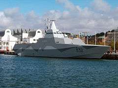
RCS reduction is chiefly important in stealth technology for aircraft, missiles, ships, and other military vehicles. With smaller RCS, vehicles can better evade radar detection, whether it be from land-based installations, guided weapons or other vehicles. Reduced signature design also improves platforms' overall survivability through the improved effectiveness of its radar counter-measures.
Several methods exist. The distance at which a target can be detected for a given radar configuration varies with the fourth root of its RCS.[11] Therefore, in order to cut the detection distance to one tenth, the RCS should be reduced by a factor of 10,000. Whilst this degree of improvement is challenging, it is often possible when influencing platforms during the concept/design stage and using experts and advanced computer code simulations to implement the control options described below.
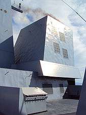
Purpose shaping
With purpose shaping, the shape of the target’s reflecting surfaces is designed such that they reflect energy away from the source. The aim is usually to create a “cone-of-silence” about the target’s direction of motion. Due to the energy reflection, this method is defeated by using Passive (multistatic) radars.
Purpose-shaping can be seen in the design of surface faceting on the F-117A Nighthawk stealth fighter. This aircraft, designed in the late 1970s though only revealed to the public in 1988, uses a multitude of flat surfaces to reflect incident radar energy away from the source. Yue suggests[12] that limited available computing power for the design phase kept the number of surfaces to a minimum. The B-2 Spirit stealth bomber benefited from increased computing power, enabling its contoured shapes and further reduction in RCS. The F-22 Raptor and F-35 Lightning II continue the trend in purpose shaping and promise to have even smaller monostatic RCS.
Active cancellation
With active cancellation, the target generates a radar signal equal in intensity but opposite in phase to the predicted reflection of an incident radar signal (similarly to noise canceling ear phones). This creates destructive interference between the reflected and generated signals, resulting in reduced RCS. To incorporate active cancellation techniques, the precise characteristics of the waveform and angle of arrival of the illuminating radar signal must be known, since they define the nature of generated energy required for cancellation. Except against simple or low frequency radar systems, the implementation of active cancellation techniques is extremely difficult due to the complex processing requirements and the difficulty of predicting the exact nature of the reflected radar signal over a broad aspect of an aircraft, missile or other target.
Radar absorbent material
Radar absorbent material (RAM) can be used in the original construction, or as an addition to highly reflective surfaces. There are at least three types of RAM: resonant, non-resonant magnetic and non-resonant large volume.
- Resonant but somewhat 'lossy' materials are applied to the reflecting surfaces of the target. The thickness of the material corresponds to one-quarter wavelength of the expected illuminating radar-wave (a Salisbury screen). The incident radar energy is reflected from the outside and inside surfaces of the RAM to create a destructive wave interference pattern. This results in the cancellation of the reflected energy. Deviation from the expected frequency will cause losses in radar absorption, so this type of RAM is only useful against radar with a single, common, and unchanging frequency.
- Non-resonant magnetic RAM uses ferrite particles suspended in epoxy or paint to reduce the reflectivity of the surface to incident radar waves. Because the non-resonant RAM dissipates incident radar energy over a larger surface area, it usually results in a trivial increase in surface temperature, thus reducing RCS without an increase in infrared signature. A major advantage of non-resonant RAM is that it can be effective over a wide range of frequencies, whereas resonant RAM is limited to a narrow range of design frequencies.
- Large volume RAM is usually resistive carbon loading added to fiberglass hexagonal cell aircraft structures or other non-conducting components. Fins of resistive materials can also be added. Thin resistive sheets spaced by foam or aerogel may be suitable for spacecraft.
Thin coatings made of only dielectrics and conductors have very limited absorbing bandwidth, so magnetic materials are used when weight and cost permit, either in resonant RAM or as non-resonant RAM.
Plasma-based RCS reduction
Plasma stealth is a proposed process to use ionized gas (plasma) to reduce the RCS of an aircraft. Interactions between electromagnetic radiation and ionized gas have been extensively studied for many purposes, including concealing aircraft from radar as stealth technology. Various methods might plausibly be able to form a layer or cloud of plasma around a vehicle to deflect or absorb radar, from simpler electrostatic or radio frequency (RF) discharges to more complex laser discharges. It is theoretically possible to reduce RCS in this way, but it may be very difficult to do so in practice.
Optimization methods
Thin non-resonant or broad resonance coatings can be modeled with a Leontovich impedance boundary condition (see also Electrical impedance). This is the ratio of the tangential electric field to the tangential magnetic field on the surface, and ignores fields propagating along the surface within the coating. This is particularly convenient when using boundary element method calculations. The surface impedance can be calculated and tested separately. For an isotropic surface the ideal surface impedance is equal to the 377 ohm impedance of free space. For non-isotropic (anisotropic) coatings, the optimal coating depends on the shape of the target and the radar direction, but duality, the symmetry of Maxwell's equations between the electric and magnetic fields, tells one that optimal coatings have η0 × η1 = 3772 Ω2, where η0 and η1 are perpendicular components of the anisotropic surface impedance, aligned with edges and/or the radar direction. A perfect electric conductor has more back scatter from a leading edge for the linear polarization with the electric field parallel to the edge and more from a trailing edge with the electric field perpendicular to the edge, so the high surface impedance should be parallel to leading edges and perpendicular to trailing edges, for the greatest radar threat direction, with some sort of smooth transition between.
To calculate the radar cross-section of such a stealth body, one would typically do one-dimensional reflection calculations to calculate the surface impedance, then two dimensional numerical calculations to calculate the diffraction coefficients of edges and small three dimensional calculations to calculate the diffraction coefficients of corners and points. The cross section can then be calculated, using the diffraction coefficients, with the physical theory of diffraction or other high frequency method, combined with physical optics to include the contributions from illuminated smooth surfaces and Fock calculations to calculate creeping waves circling around any smooth shadowed parts.
Optimization is in the reverse order. First one does high frequency calculations to optimize the shape and find the most important features, then small calculations to find the best surface impedances in the problem areas, then reflection calculations to design coatings. One should avoid large numerical calculations that run too slowly for numerical optimization or distract workers from the physics, even when massive computing power is available.
RCS of an antenna
For the case of an antenna the total RCS can be divided into two separate components as Structural Mode RCS and Antenna Mode RCS. The two components of the RCS relates to the two scattering phenomena that takes place at the antenna. When an electromagnetic signal falls on an antenna surface, some part of the electromagnetic energy is scattered back to the space. This is called structural mode scattering. The remaining part of the energy is absorbed due to the antenna effect. Some part of the absorbed energy is again scattered back into the space due to the impedance mismatches, called antenna mode scattering.[13][14][15]
See also
References
- ↑ Ulaby, Fawwaz (1986). Microwave Remote Sensing: Active and Passive, Volume 2. Artech House, Inc. p. 463. ISBN 0-89006-191-2.
- ↑ Skolnick, M.I., Introduction to Radar Systems, McGraw-Hill, 1980.
- ↑ Knott, Eugene; Shaeffer, John; Tuley, Michael (1993). Radar Cross Section, 2nd ed. Artech House, Inc. p. 231. ISBN 0-89006-618-3.
- ↑ F-22 Raptor Stealth GlobalSecurity.org
- ↑ Bill Sweetman, Unconventional Weapon: What we learned about stealth technology from the combat career of the F-117, Smithsonian Air & Space Magazine, 01 January 2008
- ↑ Radar Cross Section Measurements (8-12 GHz)
- ↑ Ship RCS Table
- ↑ www.radartutorial.eu (Effektive Rückstrahlfläche (RCS); German)
- ↑ M. Skolnik: Introduction to radar systems. 2nd Edition, McGraw-Hill, Inc., 1980, p. 44
- ↑ Balanis, C.A., Advanced Engineering Electromagnetics, John Wiley & Sons, 1989.
- ↑ Sweetman, Bill (1991). YF-22 and YF-23 Advanced Tactical Fighters: Stealth, Speed and Agility for Air Superiority. Osceola, Wisconsin, United States: Motorbooks International. ISBN 0-87938-505-7.
- ↑ The Tech (2001). "Detection of the B-2 Stealth Bomber And a Brief History on "Stealth"".
- ↑ J. A. McEntee (1957). "A technique for measuring the scattering aperture and absorption aperture of an antenna".
- ↑ SciTech Publishing (2004), Radar Cross Section
- ↑ IEEE Transactions on Antennas and Propagation (2008). "A Method to Measure Radar Cross Section Parameters of Antennas".
- Shaeffer, Tuley and Knott. Radar Cross Section. SciTech Publishing, 2004. ISBN 1-891121-25-1.
- Harrington, Roger F. Time-Harmonic Electromagnetic Fields. McGraw-Hill, Inc., 1961. ISBN 0-471-20806-X
- Balanis, Constantine A. Advanced Engineering Electromagnetics. Wiley, 1989. ISBN 0-471-62194-3.
- “A Hybrid Method Based on Reciprocity for the Computation of Diffraction by Trailing Edges”David R. Ingham, IEEE Trans. Antennas Propagat., 43 No. 11, November 1995, pp. 1173–82.
- “Revised Integration Methods in a Galerkin BoR Procedure” David R. Ingham, Applied Computational Electromagnetics Society (ACES ) Journal 10 No. 2, July, 1995, pp. 5–16.
- “A Hybrid Approach to Trailing Edges and Trailing Ends” David R. Ingham, proceedings of the ACES Symposium, 1993, Monterey.
- “Time-Domain Extrapolation to the Far Field Based on FDTD Calculations” Kane Yee, David Ingham and Kurt Shlager, IEEE Trans. Antennas Propagat., 39 No. 3, March 1991, pp. 410–413.
- “Numerical Calculation of Edge Diffraction, using Reciprocity” David Ingham, Proc. Int. Conf. Antennas Propagat., IV, May 1990, Dallas, pp. 1574–1577.
- “Time-Domain Extrapolation to the Far Field Based on FDTD Calculations”Kane Yee, David Ingham and Kurt Shlager, invited paper, Proc. URSI Conf., 1989, San José .
External links
- Hip-pocket formulas for high-frequency RCS backscatter; useful reference sheet (PDF)
- Method to measure radar cross section parameters of antennas
- Puma-EM A high performance, parallelized, open source Method of Moments / Multilevel Fast Multipole Method electromagnetics code
- Radar Cross Section Reduction Course A GA Tech course geared toward techniques used to reduce radar signature
