Pulse-Doppler radar

A pulse-Doppler radar is a radar system that determines the range to a target using pulse-timing techniques, and uses the Doppler effect of the returned signal to determine the target object's velocity. It combines the features of pulse radars and continuous-wave radars, which were formerly separate due to the complexity of the electronics.
Pulse-Doppler systems were first widely used on fighter aircraft starting in the 1960s. Earlier radars had used pulse-timing in order to determine range and the angle of the antenna (or similar means) to determine the bearing. However, this only worked when the radar antenna was not pointed down; in that case the reflection off the ground overwhelmed any returns from other objects. As the ground moves at the same speed but opposite direction of the aircraft, Doppler techniques allow the ground return to be filtered out, revealing aircraft and vehicles. This gives pulse-Doppler radars "look-down/shoot-down" capability. A secondary advantage in military radar is to reduce the transmitted power while achieving acceptable performance for improved safety of stealthy radar.[1]
Pulse-Doppler techniques also find widespread use in meteorological radars, allowing the radar to determine wind speed from the velocity of any precipitation in the air. Pulse-Doppler radar is also the basis of synthetic aperture radar used in radar astronomy, remote sensing and mapping. In air traffic control, they are used for discriminating aircraft from clutter. Besides the above conventional surveillance applications, pulse-Doppler radar has been successfully applied in healthcare, such as fall risk assessment and fall detection, for nursing or clinical purposes.[2]
History
The earliest radar systems failed to operate as expected. The reason was traced to Doppler effects that degrade performance of systems not designed to account for moving objects. Fast-moving objects cause a phase-shift on the transmit pulse that can produce signal cancellation. Doppler has maximum detrimental effect on moving target indicator systems, which must use reverse phase shift for Doppler compensation in the detector.
Doppler weather effects (precipitation) were also found to degrade conventional radar and moving target indicator radar, which can mask aircraft reflections. This phenomenon was adapted for use with weather radar in the 1950s after declassification of some World War II systems.
Pulse-Doppler radar was developed during World War II to overcome limitations by increasing pulse repetition frequency. This required the development of klystron, the traveling wave tube, and solid state devices. Pulse-Doppler is incompatible with other high power microwave amplification devices that are not coherent.
Early examples of military systems include the AN/SPG-51B developed during the 1950s specifically for the purpose of operating in hurricane conditions with no performance degradation.
The Hughes AN/ASG-18 Fire Control System was a prototype airborne radar/combination system for the planned North American XF-108 Rapier interceptor aircraft for the United States Air Force, and later for the Lockheed YF-12. The US's first pulse-Doppler radar,[3] the system had look-down/shoot-down capability and could track one target at a time.
Weather, chaff, terrain, flying techniques, and stealth are common tactics used to hide aircraft from radar. Pulse-Doppler radar eliminates these weaknesses.
It became possible to use pulse-Doppler radar on aircraft after digital computers were incorporated in the design. Pulse-Doppler provided look-down/shoot-down capability to support air-to-air missile systems in most modern military aircraft by the mid 1970s.
Principle

Range measurement
Pulse-Doppler systems measure the range to objects by measuring the elapsed time between sending a pulse of radio energy and receiving a reflection of the object. Radio waves travel at the speed of light, so the distance to the object is the elapsed time multiplied by the speed of light, divided by two - there and back.
Velocity measurement
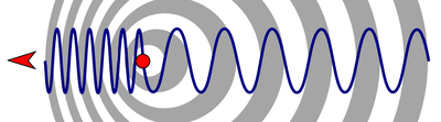
Pulse-Doppler radar is based on the Doppler effect, where movement in range produces frequency shift on the signal reflected from the target.

Radial velocity is essential for pulse-Doppler radar operation. As the reflector moves between each transmit pulse, the returned signal has a phase difference or phase shift from pulse to pulse. This causes the reflector to produce Doppler modulation on the reflected signal.
Pulse-Doppler radars exploit this phenomenon to improve performance.
The amplitude of the successively returning pulse from the same scanned volume is:

where

So

This allows the radar to separate the reflections from multiple objects located in the same volume of space by separating the objects using a spread spectrum to segregate different signals.
- where is the phase shift induced by range motion.


Benefits
Rejection speed is selectable on pulse-Doppler aircraft-detection systems so nothing below that speed will be detected. A one degree antenna beam illuminates millions of square feet of terrain at 10 miles (16 km) range, and this produces thousands of detections at or below the horizon if Doppler is not used.
Pulse-Doppler radar uses the following signal processing criteria to exclude unwanted signals from slow-moving objects. This is also known as clutter rejection.[4] Rejection velocity is usually set just above the prevailing wind speed (10 to 100 mile/hour or 15 to 150 km/hour). The velocity threshold is much lower for weather radar.[5]

In airborne pulse-Doppler radar, the velocity threshold is offset by the speed of the aircraft relative to the ground.

- Where is the angle offset between the antenna position and the aircraft flight trajectory.

Surface reflections appear in almost all radar. Ground clutter generally appears in a circular region within a radius of about 25 miles near ground-based radar. This distance extends much further in airborne and space radar. Clutter results from radio energy being reflected from the earth's surface, buildings, and vegetation. Clutter includes weather in radar intended to detect and report aircraft and spacecraft.[6]
Clutter creates a vulnerability region in pulse-amplitude time-domain radar. Non-Doppler radar systems cannot be pointed directly at the ground due to excessive false alarms, which overwhelm computers and operators. Sensitivity must be reduced near clutter to avoid overload. This vulnerability begins in the low-elevation region several beam widths above the horizon, and extends downward. This also exists throughout the volume of moving air associated with weather phenomenon.
Pulse-Doppler radar corrects this as follows.
- Allows the radar antenna to be pointed directly at the ground without overwhelming the computer and without reducing sensitivity.
- Fills in the vulnerability region associated with pulse-amplitude time-domain radar for small object detection near terrain and weather.
- Increases detection range by 300% or more in comparison to Moving target indication (MTI) by improving sub-clutter visibility.[7]
Clutter rejection capability of about 60 dB is needed for look-down/shoot-down capability, and pulse-Doppler is the only strategy that can satisfy this requirement. This eliminates vulnerabilities associated with the low-elevation and below-horizon environment.
Pulse compression, and moving target indicator (MTI) provide up to 25 dB sub-clutter visibility. MTI antenna beam is aimed above horizon to avoid excessive false alarm rate, which renders systems vulnerable. Aircraft and some missiles exploit this weakness using a technique called flying below the radar to avoid detection (Nap-of-the-earth). This flying technique is ineffective against pulse-Doppler radar.
Pulse-Doppler provides an advantage when attempting to detect missiles and low observability aircraft flying near terrain, sea surface, and weather.
Audible Doppler and target size support passive vehicle type classification when identification friend or foe is not available from a transponder signal. Medium pulse repetition frequency (PRF) reflected microwave signals fall between 1,500 and 15,000 cycle per second, which is audible. This means a helicopter sounds like a helicopter, a jet sounds like a jet, and propeller aircraft sound like propellers. Aircraft with no moving parts produce a tone. The actual size of the target can be calculated using the audible signal.
Detriments
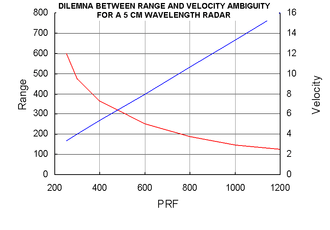
Ambiguity processing is required when target range is above the red line in the graphic, which increases scan time.
Scan time is a critical factor for some systems because vehicles moving at or above the speed of sound can travel one mile (1.6 km) every few seconds, like the Exocet, Harpoon, Kitchen, and Air-to-air missile. The maximum time to scan the entire volume of the sky must be on the order of a dozen seconds or less for systems operating in that environment.
Pulse-Doppler radar by itself can be too slow to cover the entire volume of space above the horizon unless fan beam is used. This approach is used with the AN/SPS 49(V)5 Very Long Range Air Surveillance Radar, which sacrifices elevation measurement to gain speed.[8]
Pulse-Doppler antenna motion must be slow enough so that all the return signals from at least 3 different PRF can be processed out to the maximum anticipated detection range. This is known as dwell time.[9] Antenna motion for pulse-Doppler must be as slow as radar using MTI.
Search radar that include pulse-Doppler are usually dual mode because best overall performance is achieved when pulse-Doppler is used for areas with high false alarm rates (horizon or below and weather), while conventional radar will scan faster in free-space where false alarm rate is low (above horizon with clear skies).
The antenna type is an important consideration for multi-mode radar because undesirable phase shift introduced by the radar antenna can degrade performance measurements for sub-clutter visibility.
Signal processing
The signal processing enhancement of pulse-Doppler allows small high-speed objects to be detected in close proximity to large slow moving reflectors. To achieve this, the transmitter must be coherent and should produce low phase noise during the detection interval, and the receiver must have large instantaneous dynamic range.
Pulse-Doppler signal processing also includes ambiguity resolution to identify true range and velocity.
The received signals from multiple PRF are compared to determine true range using the range ambiguity resolution process.
The received signals are also compared using the frequency ambiguity resolution process.
Range resolution
The range resolution is the minimum range separation between two objects traveling at the same speed before the radar can detect two discrete reflections.

Velocity resolution
The velocity resolution is the minimum radial velocity difference between two objects traveling at the same range before the radar can detect two discrete reflections.

Special consideration
Pulse-Doppler radar has special requirements that must be satisfied to achieve acceptable performance.
Pulse repetition frequency
Pulse-Doppler typically uses medium pulse repetition frequency (PRF) from about 3 kHz to 30 kHz. The range between transmit pulses is 5 km to 50 km.
Range and velocity cannot be measured directly using medium PRF, and ambiguity resolution is required to identify true range and speed. Doppler signals are generally above 1 kHz, which is audible, so audio signals from medium-PRF systems can be used for passive target classification.
Angular measurement
Radar systems require angular measurement. Transponders are not normally associated with pulse-Doppler radar, so sidelobe suppression is required for practical operation.[10][11]
Tracking radar systems use angle error to improve accuracy by producing measurements perpendicular to the radar antenna beam. Angular measurements are averaged over a span of time and combined with radial movement to develop information suitable to predict target position for a short time into the future.
The two angle error techniques used with tracking radar are monopulse and conical scan.
Coherency
Pulse-Doppler radar requires a coherent oscillator with very little noise. Phase noise reduces sub-clutter visibility performance by producing apparent motion on stationary objects.
Cavity magnetron and crossed-field amplifier are not appropriate because noise introduced by these devices interfere with detection performance. The only amplification devices suitable for pulse-Doppler are klystron, traveling wave tube, and solid state devices.
Scalloping
Pulse-Doppler signal processing introduces a phenomenon called scalloping. The name is associated with a series of holes that are scooped-out of the detection performance.
Scalloping for pulse-Doppler radar involves blind velocities created by the clutter rejection filter. Every volume of space must be scanned using 3 or more different PRF. A two PRF detection scheme will have detection gaps with a pattern of discrete ranges, each of which has a blind velocity.
Windowing
Ringing artifacts pose a problem with search, detection, and ambiguity resolution in pulse-Doppler radar.
Ringing is reduced in two ways.
First, the shape of the transmit pulse is adjusted to smooth the leading edge and trailing edge so that RF power is increased and decreased without an abrupt change. This creates a transmit pulse with smooth ends instead of a square wave, which reduces ringing phenomenon that is otherwise associated with target reflection.
Second, the shape of the receive pulse is adjusted using a window function that minimizes ringing that occurs any time pulses are applied to a filter. In a digital system, this adjusts the phase and/or amplitude of each sample before it is applied to the Fast Fourier Transform. The Dolph-Chebyshev window is the most effective because it produces a flat processing floor with no ringing that would otherwise cause false alarms.[12]
Antenna
Pulse-Doppler radar is generally limited to mechanically aimed antennas and active phase array.
Mechanical RF components, such as wave-guide, can produce Doppler modulation due to phase shift induced by vibration. This introduces a requirement to perform full spectrum operational tests using shake tables that can produce high power mechanical vibration across all anticipated audio frequencies.
Doppler is incompatible with most electronically steered phase-array antenna. This is because the phase-shifter elements in the antenna are non-reciprocal and the phase shift must be adjusted before and after each transmit pulse. Spurious phase shift is produced by the sudden impulse of the phase shift, and settling during the receive period between transmit pulses places Doppler modulation onto stationary clutter. That receive modulation corrupts the measure of performance for sub-clutter visibility. Phase shifter settling time on the order of 50ns is required. Start of receiver sampling needs to be postponed at least 1 phase-shifter settling time-constant (or more) for each 20 dB of sub-clutter visibility.
Most antenna phase shifters operating at PRF above 1 kHz introduce spurious phase shift unless special provisions are made, such as reducing phase shifter settling time to a few dozen nanoseconds.[13]
The following gives the maximum permissible settling time for antenna phase shift modules.

where
- T = phase shifter settling time
- SCV = sub-clutter visibility in dB
- S = number of range samples between each transmit pulse
- PRF = maximum design pulse repetition frequency
The antenna type and scan performance is a practical consideration for multi-mode radar systems.
Diffraction
Choppy surfaces, like waves and trees, form a diffraction grating suitable for bending microwave signals. Pulse-Doppler can be so sensitive that diffraction from mountains, buildings or wave tops can be used to detect fast moving objects otherwise blocked by solid obstruction along the line of sight. This is a very lossy phenomenon that only becomes possible when radar has significant excess sub-clutter visibility.
Refraction and ducting use transmit frequency at L-band or lower to extend the horizon, which is very different from diffraction. Refraction for over-the-horizon radar uses variable density in the air column above the surface of the earth to bend RF signals. An inversion layer can produce a transient troposphere duct that traps RF signals in a thin layer of air like a wave-guide.
Subclutter visibility
Subclutter visibility involves the maximum ratio of clutter power to target power, which is proportional to dynamic range. This determines performance in heavy weather and near the earth surface.

Subclutter visibility is the ratio of the smallest signal that can be detected in the presence of a larger signal.

A small fast-moving target reflection can be detected in the presence of larger slow-moving clutter reflections when the following is true.

Performance
The pulse-Doppler radar equation can be used to understand trade-offs between different design constraints, like power consumption, detection range, and microwave safety hazards. This is a very simple form of modeling that allows performance to be evaluated in a sterile environment.
The theoretical range performance is as follows.

where
- R = Distance to the target
- Pt = Transmitter power
- Gt = Gain of the transmitting antenna
- Ar = Effective aperture (area) of the receiving antenna
- σ = Radar cross section, or scattering coefficient, of the target
- F = Antenna pattern propagation factor
- D = Doppler filter size (transmit pulses in each Fast Fourier transform)
- Kb = Boltzmann's constant
- T = Temperature (kelvin)
- B = Receiver Bandwidth (band pass filter)
- N = Noise figure
This equation is derived by combining the Radar equation with the Noise equation and accounting for in-band noise distribution across multiple detection filters. The value D is added to the standard radar range equation to account for both pulse-Doppler signal processing and transmitter FM noise reduction.
Detection range is increased proportional to the square root of the number of filters. Power consumption is reduced by the square of the number of filers.
Pulse-Doppler signal processing integrates all of the energy from all of the individual reflected pulses that enter the filter. This means a pulse-Doppler signal processing system with 1,024 elements provides 30.103 dB of improvement due to the type of signal processing that must be used with pulse-Doppler radar. The energy of all of the individual pulses from the object are added together by the filtering process.
Signal processing for a 1,024 point filter improves performance by 30.103 dB, assuming compatible transmitter and antenna. This corresponds to the following potential improvements.
- 562% increase in maximum distance.
These improvements are the reason pulse-Doppler is essential for military and astronomy.
Aircraft tracking uses
Pulse-Doppler radar for aircraft detection has two modes.
- Scan
- Track
Scan mode involves frequency filtering, amplitude thresholding, and ambiguity resolution. Once a reflection has been detected and resolved, the pulse-Doppler radar automatically transitions to tracking mode for the volume of space surrounding the track.
Track mode works like a phase-locked loop, where Doppler velocity is compared with the range movement on successive scans. Lock indicates the difference between the two measurements is below a threshold, which can only occur with an object that satisfies Newtonian mechanics. Other types of electronic signals cannot produce a lock. Lock exists in no other type of radar.
The lock criteria needs to be satisfied during normal operation.[14]
Lock eliminates the need for human intervention with the exception of helicopters and electronic jamming.
Weather phenomenon obey adiabatic process associated with air mass and not Newtonian mechanics, so the lock criteria is not normally used for weather radar.
Pulse-Doppler signal processing selectively excludes low-velocity reflections so that no detections occurs below a threshold velocity. This eliminates terrain, weather, biologicals, and mechanical jamming with the exception of decoy aircraft.
The target Doppler signal from the detection is converted from frequency domain back into time domain sound for the operator in track mode on some radar systems. The operator uses this sound for passive target classification, such as recognizing helicopters and electronic jamming.
Helicopters
Special consideration is required for aircraft with large moving parts because pulse-Doppler radar operates like a phase-locked loop. Blade tips moving near the speed of sound produce the only signal that can be detected when a helicopter is moving slow near terrain and weather.
Helicopters appears like a rapidly pulsing noise emitter except in a clear environment free from clutter. An audible signal is produced for passive identification of the type of airborne object. Microwave Doppler frequency shift produced by reflector motion falls into the audible sound range for human beings (20-20,000 Hz), which is used for target classification in addition to the kinds of conventional radar display used for that purpose, like A-Scope, B-Scope, C-Scope, and RHI indicator. The human ear may be able to tell the difference better than electronic equipment.
A special mode is required because the Doppler velocity feedback information must be unlinked from radial movement so that the system can transition from scan to track with no lock.
Similar techniques are required to develop track information for jamming signals and interference that cannot satisfy the lock criteria.
Multi-mode
Pulse-Doppler radar must be multi-mode to handle aircraft turning and crossing trajectory.
Once in track mode, pulse-Doppler radar must include a way to modify Doppler filtering for the volume of space surrounding a track when radial velocity falls below the minimum detection velocity. Doppler filter adjustment must be linked with a radar track function to automatically adjust Doppler rejection speed within the volume of space surrounding the track.
Tracking will cease without this feature because the target signal will otherwise be rejected by the Doppler filter when radial velocity approaches zero.
Multi-mode operation may also include continuous wave illumination for semi-active radar homing.
See also
- Radar signal characteristics (fundamentals of the radar signal)
- Doppler radar (non-pulsed; used for navigation systems)
- Weather radar (pulsed with Doppler processing)
- Continuous-wave radar (non-pulsed, pure Doppler processing)
- Fm-cw radar (non-pulsed, swept frequency, range and Doppler processing)
- Aliasing - the reason for ambiguous velocity estimates
- Doppler sonography - velocity measurements in medical ultrasound. Based on the same principle
- Tartar Guided Missile Fire Control System
- AN/SPS-49 surface search radar (US)
- AN/SPG-51D, the MK-74 Guided Missile Fire Control System (US)
- MK-74 Guided Missile Fire Control System (GMFCS) (US)
- McDonnell Douglas F-15 Eagle radar system (US)
- General Dynamics F-16 Fighting Falcon radar system (US)
- Close-in weapon system (US)
- Mirage (French)
- Smerch (radar) (Soviet)
- Zaslon (Soviet)
- Type 345 Radar (Chinese)
- CLC-1 Radar (Chinese)
- SLC-2 Radar (Chinese)
- YLC-15 Radar (Chinese)
- JL-10A (Chinese)
- KLJ-7 Radar (Chinese)
- Doppler On Wheels, meteorological
- NEXRAD, meteorological
- Terminal Doppler Weather Radar, meteorological
- ARMOR Doppler Weather Radar, meteorological
External links
- Doppler radar presentation, which highlights the advantages of using the autocorrelation technique
- Pulse-Doppler radar handouts from Introduction to Principles and Applications of Radar course at University of Iowa
- Modern Radar Systems by Hamish Meikle (ISBN 1-58053-294-2)
- Advanced Radar Techniques and Systems edited by Gaspare Galati (ISBN 0-86341-172-X)
References
- ↑ "AN/APQ-174/186 Multi-Mode Radar". Raytheon.
- ↑ "Automatic fall detection based on Doppler radar motion signature". IEEE PervasiveHealth.
- ↑ Pace 1991, p. 152.
- ↑ "Clutter Rejection (Pulse Doppler), Radar Systems Engineering". IEEE New Hampshire Section, University of New Hampshire.
- ↑ "Path to Nexrad, Doppler Radar Development at the National Severe Storm Laboratory" (PDF). National Oceanic and Atmospheric Administration, National Severe Storm Laboratory.
- ↑ "How does Doppler Radar Work?". Weather Beacon Doppler Radar.
- ↑ "Subclutter Visibility and Improvement Factor". Retrieved January 29, 2011.
- ↑ "AN/SPS-49 Very Long-Range Air Surveillance Radar". Federation of American Scientists.
- ↑ "Dwell Time and Hits Per Scan". Radartutorial.
- ↑ "Side Lobe Suppression". Radartutorial.eu.
- ↑ "Side Lobe Suppression". Massachusetts Institute of Technology.
- ↑ "Dolph-Chebyshev Window". Stanford University. Retrieved January 29, 2011.
- ↑ "High Power L Band Fast Phase Shifter" (PDF). Retrieved August 2, 2011.
- ↑ "AWACS Surveillance Radar" (PDF). Norhrop Grummond.
Bibliography
- Pace, Steve (1991). X-Fighters: USAF Experimental and Prototype Fighters, XP-59 to YF-23. St. Paul, Minnesota: Motorbooks International. ISBN 0-87938-540-5.