MOS Technology 6507

The 6507 is an 8-bit microprocessor from MOS Technology, Inc.
It is essentially a 6502 chip in a smaller, cheaper 28-pin package. To do this, A15 to A13 and some other signals such as the interrupt lines are not accessible. As a result, it can only address 8 KB of memory, which for some applications at the time (1975) was acceptable and not overly restrictive.
The 6507 and 6502 chips use the same underlying silicon layers, and differ only in the final metallisation layer. This ties the interrupt lines to their inactive level so that they are not vulnerable to generating spurious interrupts from noise. The first three digits of the chip identifier are part of the silicon layers, and the final digit is in the metallisation layer. Micro-photography of the 6502 and 6507 shows this difference.[1]
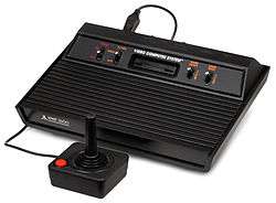
The 6507 was only widely used in two applications, the best-selling Atari 2600 video game console and the Atari 8-bit family floppy disk controllers for the 810 and 1050 drives. In the 2600, the system was further limited by the design of the ROM cartridge slot, which allowed for only 4KB of external memory to be addressed (the other 4KB was reserved for the internal RAM and I/O chip).
Most other machines, notably home computers based on the 650x architecture, used either the standard 6502 or extended, rather than cut down, versions of it, in order to allow for more memory.
By the time the 6502 line was becoming widely used around 1980, ROM and RAM semiconductor memory prices had fallen to the point where the 6507 was no longer a worthwhile simplification; its use in new designs ceased at that point, though the Atari 2600 that contained it continued to be sold into the early 1990s, as it wasn't discontinued until January 1, 1992.
Pin configuration
| /RES | 1 | 28 | Ph2 out |
| Vss | 2 | 27 | Ph0 in |
| RDY | 3 | 26 | R/W |
| Vcc | 4 | 25 | D0 |
| A0 | 5 | 24 | D1 |
| A1 | 6 | 23 | D2 |
| A2 | 7 | 22 | D3 |
| A3 | 8 | 21 | D4 |
| A4 | 9 | 20 | D5 |
| A5 | 10 | 19 | D6 |
| A6 | 11 | 18 | D7 |
| A7 | 12 | 17 | A12 |
| A8 | 13 | 16 | A11 |
| A9 | 14 | 15 | A10 |
The 6507 uses a 28-pin configuration, with 13 address pins and 8 data pins. The seven remaining pins are used for power, the CPU timing clock, to reset the CPU, to request bus wait states, and for read/write commands to memory (or MMIO devices) from the CPU. There is no IRQ or NMI pin on the processor.
References
- ↑ Visual6502. "Visual6502.org: 6502 vs. 6507".
- ↑ Peter Turnbull (January 25, 2005). "MOS 6507 Tech Spec's".
