Instant centre of rotation
The instant centre of rotation, also called instantaneous velocity center,[1] or also instantaneous centre or instant centre, is the point fixed to a body undergoing planar movement that has zero velocity at a particular instant of time. At this instant, the velocity vectors of the trajectories of other points in the body generate a circular field around this point which is identical to what is generated by a pure rotation.
Planar movement of a body is often described using a plane figure moving in a two-dimensional plane. The instant centre is the point in the moving plane around which all other points are rotating at a specific instant of time.
The continuous movement of a plane has an instant centre for every value of the time parameter. This generates a curve called the moving centrode. The points in the fixed plane corresponding to these instant centres form the fixed centrode.
Pole of a planar displacement
The instant centre can be considered the limiting case of the pole of a planar displacement.
The planar displacement of a body from position 1 to position 2 is defined by the combination of a planar rotation and planar translation. For any planar displacement there is a point in the moving body that is in the same place before and after the displacement. This point is the pole of the planar displacement, and the displacement can be viewed as a rotation around this pole.
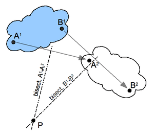
Construction for the pole of a planar displacement: First, select two points A and B in the moving body and locate the corresponding points in the two positions; see the illustration. Construct the perpendicular bisectors to the two segments A1A2 and B1B2. The intersection P of these two bisectors is the pole of the planar displacement. Notice that A1 and A2 lie on a circle around P. This is true for the corresponding positions of every point in the body.
If the two positions of a body are separated by an instant of time in a planar movement, then the pole of a displacement becomes the instant centre. In this case, the segments constructed between the instantaneous positions of the points A and B become the velocity vectors VA and VB. The lines perpendicular to these velocity vectors intersect in the instant centre.
Pure translation
If the displacement between two positions is a pure translation, then the perpendicular bisectors of the segments A1B1 and A2B2 form parallel lines. These lines are considered to intersect at a point on the line at infinity, thus the pole of this planar displacement is said to "lie at infinity" in the direction of the perpendicular bisectors.
In the limit, pure translation becomes planar movement with point velocity vectors that are parallel. In this case, the instant centre is said to lie at infinity in the direction perpendicular to the velocity vectors.
Instant centre of a wheel rolling without slipping
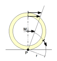
Consider the planar movement of a circular wheel rolling without slipping on a linear road; see sketch 3. The wheel rotates around its axis M, which translates in a direction parallel to the road. The point of contact P of the wheel with road does not slip, which means the point P has zero velocity with respect to point M. Thus, at the instant the point P on the wheel comes in contact with the road it becomes an instant centre.
The set of points of the moving wheel that become instant centres is the circle itself, which defines the moving centrode. The points in the fixed plane that correspond to these instant centres is the line of the road, which defines the fixed centrode.
The velocity vector of a point A in the wheel is perpendicular to the segment AP and is proportional to the length of this segment. In particular, the velocities of points in the wheel are determined by the angular velocity of the wheel in rotation around P. The velocity vectors of a number of points are illustrated in sketch 3.
The further a point in the wheel is from the instant centre P, the proportionally larger its speed. Therefore, the point at the top of the wheel moves in the same direction as the centre M of the wheel, but twice as fast, since it is twice the distance away from P. All points that are a distance equal to the radius of the wheel 'r' from point P move at the same speed as the point M but in different directions. This is shown for a point on the wheel that has the same speed as M but moves in the direction tangent to the circle around P.
Relative centre of rotation for two contacting planar bodies
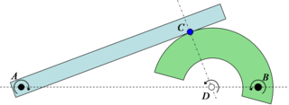
If two planar rigid bodies are in contact, and each body has its own distinct centre of rotation, then the relative centre of rotation between the bodies has to lie somewhere on the line connecting the two centres. As a result, since pure rolling can only exist when the centre of rotation is at the point of contact (as seen above with the wheel on the road), it is only when the point of contact goes through the line connecting the two rotation centres that pure rolling can be achieved. This is known in involute gear design as the pitch point, where there is no relative sliding between the gears. In fact, the gearing ratio between the two rotating parts is found by the ratio of the two distances to the relative centre. In the example in Sketch 4 the gearing ratio is

Instant centre of rotation and mechanisms
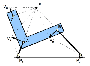
Sketch 1 above shows a four-bar linkage where a number of instant centres of rotation are illustrated. The rigid body noted by the letters BAC is connected with links P1-A and P2-B to a base or frame.
The three moving parts of this mechanism (the base is not moving) are: link P1-A, link P2-B, and body BAC. For each of these three parts an instant centre of rotation may be determined.
Considering first link P1-A: all points on this link, including point A, rotate around point P1. Since P1 is the only point not moving in the given plane it may be called the instant centre of rotation for this link. Point A, at distance P1-A from P1, moves in a circular motion in a direction perpendicular to the link P1-A, as indicated by vector VA.
The same applies to link P2-B: point P2 is the instant centre of rotation for this link and point B moves in the direction as indicated by vector VB.
For determining the instant centre of rotation of the third element of the linkage, the body BAC, the two points A and B are used because its moving characteristics are known, as derived from the information about the links P1-A and P2-B.
The direction of speed of point A is indicated by vector VA. Its instant centre of rotation must be perpendicular to this vector (as VA is tangentially located on the circumference of a circle). The only line that fills the requirement is a line colinear with link P1-A. Somewhere on this line there is a point P, the instant centre of rotation for the body BAC.
What applies to point A also applies to point B, therefore this instant centre of rotation P is located on a line perpendicular to vector VB, a line colinear with link P2-B. Therefore, the instant centre of rotation P of body BAC is the point where the lines through P1-A and P2-B cross.
Since this instant centre of rotation P is the centre for all points on the body BAC for any random point, say point C, the speed and direction of movement may be determined: connect P to C. The direction of movement of point C is perpendicular to this connection. The speed is proportional to the distance to point P.
Continuing this approach with the two links P1-A and P2-B rotating around their own instant centres of rotation the centrode for instant centre of rotation P may be determined. From this the path of movement for C or any other point on body BAC may be determined.
Examples of application
In biomechanical research the instant centre of rotation is observed for the functioning of the joints in the upper and lower extremities.[2] For example, in analysing the knee,[3][4][5] ankle,[6] or shoulder joints.[7][8] Such knowledge assists in developing artificial joints and prosthesis, such as elbow [9] or finger joints.[10]
Study of the joints of horses: "...velocity vectors determined from the instant centres of rotation indicated that the joint surfaces slide on each other.".[11]
Studies on turning a vessel moving through water.[12]
The braking characteristics of a car may be improved by varying the design of a brake pedal mechanism.[13]
Designing the suspension of a bicycle,[14] or of a car.[15]
In the case of the coupler link in a four-bar linkage, such as a double wishbone suspension in front view, the perpendiculars to the velocity lie along the links joining the grounded link to the coupler link. This construction is used to establish the kinematic Roll centre of the suspension.
References
- ↑ Illustrated Dictionary of Mechanical Engineering: English, German, French, Dutch, Russian (Springer Science & Business Media, 17 Apr. 2013 - 422 pages)
- ↑ "Muscle Physiology — Joint Moment Arm".
- ↑ Knee joint motion description and measurement
- ↑ Moorehead JD, Montgomery SC, Harvey DM (Sep 2003). "Instant centre of rotation estimation using the Reuleaux technique and a Lateral Extrapolation technique". J Biomechanics. 36 (9): 1301–7. doi:10.1016/S0021-9290(03)00156-8. PMID 12893038.
- ↑ Hollman JH, Deusinger RH, Van Dillen LR, Matava MJ (Aug 2003). "Gender differences in surface rolling and gliding kinematics of the knee". Clin Orthop Relat Res. 413 (413): 208–21. doi:10.1097/01.blo.0000072902.36018.fe. PMID 12897612.
- ↑ Maganaris CN, Baltzopoulos V, Sargeant AJ (Aug 1998). "Changes in Achilles tendon moment arm from rest to maximum isometric plantarflexion: in vivo observations in man". J Physiology. 510 (Pt 3): 977–85. doi:10.1111/j.1469-7793.1998.977bj.x. PMC 2231068
 . PMID 9660906.
 - ↑ Biomechanics of shoulder
- ↑ Poppen NK, Walker PS (Mar 1976). "Normal and abnormal motion of the shoulder". J Bone Joint Surg Am. 58 (2): 195–201. PMID 1254624.
- ↑ US 5030237 Elbow prosthesis
- ↑ Pyrocarbon Finger Joint Implant
- ↑ Colahan P, Piotrowski G, Poulos P (Sep 1988). "Kinematic analysis of the instant centres of rotation of the equine metacarpophalangeal joint". Am J Vet Res. 49 (9): 1560–5. PMID 3223666.
- ↑ PART VI Vessel Navigation and Manoeuvering
- ↑ GB 1443270 Variable Mechanical Ratio Brake Pedal Mounts - General Motors, 1976
- ↑ US 7100930 Bicycle rear suspension system
- ↑ Reza N. Jazar (2008). Vehicle Dynamics: Theory and Application. Berlin: Springer. ISBN 0-387-74243-3.
