Clipping (audio)
Clipping is a form of waveform distortion that occurs when an amplifier is overdriven and attempts to deliver an output voltage or current beyond its maximum capability. Driving an amplifier into clipping may cause it to output power in excess of its power rating.
Overview
When an amplifier is pushed to create a signal with more power than its power supply can produce, it will amplify the signal only up to its maximum capacity, at which point the signal can be amplified no further. As the signal simply "cuts" or "clips" at the maximum capacity of the amplifier, the signal is said to be "clipping". The extra signal which is beyond the capability of the amplifier is simply cut off, resulting in a sine wave becoming a distorted square-wave-type waveform.
Many electric guitar players intentionally overdrive their guitar amplifiers to cause clipping and other distortion in order to get a desired sound.
Amplifiers have voltage, current and thermal limits. Clipping may occur due to limitations in the power supply or the output stage. Some amplifiers are able to deliver peak power without clipping for short durations before energy stored in the power supply is depleted or the amplifier begins to overheat.
Effects


In power amplifiers, the signal from an amplifier operating in clipping has two characteristics that could damage a connected loudspeaker:
- Because the clipped waveform has more area underneath it than the smaller maximum unclipped waveform, the amplifier produces more output power. This extra power can cause damage to loudspeaker components, including the woofer, tweeter, or crossover, via overheating.
- In the frequency domain, clipping produces harmonics at higher frequencies than the unclipped signal. This additional high frequency energy has the potential to damage a loudspeaker via overheating.
As a result, many amplifier designers have incorporated circuits to prevent clipping. Such circuits compare the input signal to the output signal to detect the presence of extra power caused by distortion. The simplest circuits act like a fast limiter, which engages after about one decibel of clipping is detected. A more complex circuit, called "soft-clip", was used from the 1980s onward to limit the signal at the input stage. The soft-clip feature begins to engage prior to clipping, for instance starting at 10 dB below maximum output power. The output waveform retains a rounded characteristic even in the presence of an overload input signal as much as 10 dB higher than maximum specified.[1][2]
Digital clipping

In digital signal processing, clipping occurs when the signal is restricted by the range of a chosen representation. For example in a system using 16-bit signed integers, 32767 is the largest positive value that can be represented, and if during processing the amplitude of the signal is doubled, sample values of, for instance, 32000 should become 64000, but instead they are truncated to the maximum, 32767. Clipping is preferable to the alternative in digital systems—wrapping—which occurs if the digital hardware is allowed to "overflow", ignoring the most significant bits of the magnitude, and sometimes even the sign of the sample value, resulting in gross distortion of the signal.
Avoiding clipping
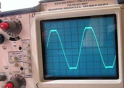
As seen on the oscilloscope, the wave resulting from the clipping is not a full sine wave. To avoid this, the overall level of a mix can be lowered, or a limiter can be used to dynamically bring the levels of the loud parts down (for example, bass and snare drums).
It is not simple to eliminate all clipping, as filtering (e.g. a high-pass filter) can align various frequencies in such a way as to create excessive peak outputs. The excessive peaks may become clipped even though the amplifier can play any single sine wave without clipping. As such, some audiophiles will use amplifiers that are rated for power outputs over twice the speaker's ratings.
Repairing a clipped signal
It is preferable to avoid clipping, but if a recording has clipped, and cannot be re-recorded, repair is an option. The goal of repair is to make up a plausible replacement for the clipped part of the signal.
Complex hard-clipped signals (recorded at CD resolution or less) cannot be restored to their original state because the information contained in the peaks that are clipped is completely eliminated. Soft-clipped signals can be restored to their original state to within a case-dependent tolerance because no part of the original signal is completely eliminated. In this case, the degree of information loss is proportional to the degree of compression caused by the clipping. Lightly clipped bandwidth-limited signals that are highly oversampled have a high likelihood of perfect repair.[3]
Several methods can partially restore a clipped signal. Once the clipped portion is known, one can attempt partial recovery. One such method is interpolation or extrapolation of known samples. While this is only an approximation of the original, the subjective quality is usually improved, sometimes with no audible difference.
Other methods may also be used. One of the methods in CuteStudio Declip, for example, works by copying the signal directly from one stereo channel to another, as it may be the case that only one channel is clipped.
Several software solutions of varying results and methods exist to counteract this problem: Sony Sound Forge, iZotope Rx3, Adobe Audition, Nero Wave Editor, and a plugin in the Audacity LADSPA package come with clip restoration software. There is also an Audacity plugin called Clip Fix that uses cubic splines to attempt to restore a continuously differentiable signal.
Sources
In analog audio equipment, there are several causes of clipping:
- The peak-to-peak of a solid-state transformerless amplifier (most integrated circuit and discrete solid state circuits) is limited to the power supply voltage less a small amount that depends on the design of the circuit (especially the driver configuration) and the saturation voltage (Vce(sat) for bipolar transistors, or Rds(on) for Field Effect Transistors), and further reduced if the output stage does not have a quiescent DC output voltage set to half the supply voltage. For example, with a typical operational amplifier the Absolute Maximum Rating for the supply voltage is 36 volts, but a safe operating design supply voltage is 30 volts; if this was supplied as a perfectly balanced +15V and -15V then the theoretical peak output for an ideal rail-to-rail output opamp would be 15 Volts peak (10.6V RMS, 30V peak-to-peak), but a real-world opamp such as the 741 is likely to only be able to drive about 10 volts peak into loads above 2 kilohms, i.e. about 7.1V RMS).
- An amplifier may have an asymmetrical output swing, perhaps because a transistor is biased so its collector voltage is not half the supply voltage (or the "balanced" power supply rails aren't perfectly balanced); clipping may begin earlier on one half of the output waveform. Bootstrapping or a redesign of the circuit may alleviate this when it is caused by difficulties in driving emitter follower output stages.
- If the power supply capacitor is no longer able to keep the voltage "flat" due to a massive current draw, the positive and negative voltage supply of the amplifier will fluctuate resulting in sort of a clipped signal that contains some AC line frequency harmonics.
- A vacuum tube can only move a limited number of electrons in an amount of time, dependent on its size, temperature, and metals. Usually fall-off in amplification with increasing output current results in "soft clipping".
- Amplifying devices may also have limits on their inputs, for example the maximum base current a bipolar transistor can take, and a vacuum tube may have problems with grid current if the input signal becomes too positive. These factors can distort (clip) the input signal, if it comes from a high enough impedance source, or destroy the device (and so the designer will probably employ other limiting circuits; see below).
- A transformer (most commonly used between stages in tube equipment) will clip when its ferromagnetic core becomes electromagnetically saturated.
- An amplifier can limit the current output, or the input voltage, for a variety of reasons both intentional or not. Intentional limiting circuits would not be expected to come into effect in normal operation, but when the output load resistance is too low or the system is connected to an exceptionally high signal level, for example. The result of this form of clipping might not create a flat top to the Voltage waveform, but rather a flat top to the current waveform.
- Certain signal processing elements can produce a unique form of phase-inverted clipping when the input signal exceeds the common-mode input range of an opamp. The result is that the voltage waveform clips, but in the wrong direction.
Some audiophiles believe that the clipping behavior of vacuum tubes (especially when used with little or no negative feedback) is superior to that of transistors, in that vacuum tubes clip more gradually than transistors, resulting in harmonic distortion that is generally less objectionable. This gradual onset of clipping is known as gain compression or "soft clipping". Circuits can be designed using either tubes or transistors to achieve this effect, and the behavior can be simulated with digital processing.
Detection
Clipping in a circuit can be detected by comparing the original input signal with an output signal that has been adjusted for changes in applied gain. For instance, if a circuit has 10 dB of applied gain, it can be tested for clipping by attenuating the output signal's gain by 10 dB and comparing it to the input signal. If the circuit is driven into clipping, the attenuated output signal will show less voltage in the comparison. The electrical offset between the two signals can be used to illuminate clipping detection indicators, such as a red LED, and can be used to decrease the gain of a preceding circuit so that the level of clipping distortion can be limited.[4]
See also
References
- ↑ Duncan, Ben (1996). High Performance Audio Power Amplifiers. Newnes. pp. 79–80. ISBN 9780080508047.
- ↑ Duncan, Ben (2009). "Interfacing and Processing". In Douglas Self; Ben Duncan; Ian Sinclair; Richard Brice; John Linsley Hood; Andrew Singmin; Don Davis; Eugene Patronis; John Watkinson. Audio Engineering: Know It All. Know It All. 1. Newnes. p. 278. ISBN 9780080949642.
- ↑ Donoho, David L.; Philip B. Stark (June 1989). "Uncertainty principles and signal recovery". SIAM Journal on Applied Mathematics. Society for Industrial and Applied Mathematics. 49 (3): 906–931. doi:10.1137/0149053. ISSN 0036-1399.
- ↑ U.S. Patent 5,430,409 "Amplifier clipping distortion indicator with adjustable supply dependence"
