Zero-ohm link

A zero-ohm link or zero-ohm resistor is a wire link used to connect traces on a printed circuit board that is packaged in the same physical package format as a resistor. This format allows it to be placed on the circuit board using the same automated equipment used to place other resistors, instead of requiring a separate machine to install a jumper or other wire.[1] Zero-ohm resistors may be packaged like cylindrical resistors, or like surface-mount resistors.
One use is to allow traces on the same side of a PCB to cross: one trace has a zero-ohm resistor while the second trace runs in between the leads of the resistor, avoiding contact with the first trace.
The resistance is only approximately zero; only a maximum (typically 10–50 mΩ) is specified.[2] A percentage tolerance would not make sense, as it would be specified as a percentage of the ideal value of zero ohms (which would always be zero), so it is not specified.
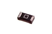
An axial-lead through-hole zero-ohm resistor is generally marked with a single black band,[3] the symbol for "0" in the resistor color code. Surface-mount resistors are generally marked with a single "0" or "000".
Design considerations
In practice, zero-ohm resistors can be useful as configuration jumpers, but caution is exercised for PCB designs which may use zero-ohm resistors to select between options which require larger trace currents in the design. For these situations, it is better design practice to specify a specific low-ohm resistance, such as a 0.001-ohm to 0.003-ohm resistor, rather than the generic "zero-ohm" resistor in which the actual resistance may be higher, and tolerance is not given. The low-ohm resistors are easily obtained with 5% or 1% tolerances on a maximum specified resistance and can be safely utilized to pass much higher currents.
For example, a surface-mounted 0805 size resistor of 0.003 ohms, rated at 1/2 watt can, in theory, safely pass up to 12.9 amperes of current. In practice, when approaching the power limit for a given package, it is good practice to either use an even lower-ohm product (more power-efficient but more expensive) or go up one package size larger (same power efficiency but cost may be kept lower). The "cost" associated with taking up more board space for the larger package may also be a consideration. In this example, for 12 amperes to pass through the jumper, a lower resistance or a bigger surface-mount package (such as a 1206) are usually specified. In contrast, a "worst-case zero-ohm" real-world jumper with 0.05-ohm impedance in a similar 0805 package could only pass 3.1 amperes maximum. The use of specific tolerance resistances is a much safer design practice for higher currents than the "zero-ohm" option, although the bill-of-materials cost can be higher for low-ohm devices.
Why use them?
Makes it easy to break circuits and isolate them to determine circuit faults you can test an unloaded output and also drive the input with a signal if you need. eg.- In a board with several channels of similar processing blocks ending in a A/D converter. By making every block separable I was able to jumper them and mix and match to find the noisy blocks in the noisy channels that had some crosstalk. Once finding the crosstalking channels it was easy to find the offending traces. You can do this troubleshooting without cutting up the board after which it is still harder to solder wires to cut traces than to solder to small SMT pads.
Test points: they are much easier to probe (no solder mask and much bigger than 5 mil traces) and not much costlier than a small pad. make options with a lot less space and cost than DIP switches and Jumper headers. You would make these options that are not changed by the end user but can be enabled or disabled for various versions (that are sold with fewer features) during assembly and or testing. enabling or disabling options at assembly time can make multiple variants of a board using a single PCB design but with different BOM.
In real cheap boards they are often used for jumpers to get over or under a trace, saving PCB routing layers.
Makes it easy to place a non-zero resistor where you might need a series resistor but are not sure about it later. Or even an chip inductor (low pass filter) or a chip capacitor (AC coupling).
Used as Jumpers SMD resistors are often lower cost than a wire connecting two holes in the board. They can be inserted by the pick and place that does the PCB assembly, whereas a wire jumper requires manual soldering. A machine may be able to auto pick and place 100,000 chips per hour vs. 30 seconds of manual labor to cut, bend, insert, and solder the wire. Depending on the labor rate in the region of manufacture, this manual soldering operation may add significant cost.
References
- ↑ Blackwell, Glenn R.; Hollomon, James K. (2006). Surface-mount technology for PC boards (2nd ed.). Australia: Thomson Delmar Learning. p. 88. ISBN 978-1-4180-0011-0.
- ↑ Archambeault, Bruce R.; Drewniak, James (2002). PCB Design for Real-World EMI Control. Springer. p. 168. ISBN 978-1-4020-7130-0.
- ↑ Paynter, Robert T.; Boydell, Toby (2008). Electronics Technology Fundamentals: Conventional Flow Version (3rd ed.). Prentice Hall. p. 50. ISBN 978-0-13-504874-0.