Wire drawing

Wire drawing is a metalworking process used to reduce the cross-section of a wire by pulling the wire through a single, or series of, drawing die(s). There are many applications for wire drawing, including electrical wiring, cables, tension-loaded structural components, springs, paper clips, spokes for wheels, and stringed musical instruments. Although similar in process, drawing is different from extrusion, because in drawing the wire is pulled, rather than pushed, through the die. Drawing is usually performed at room temperature, thus classified as a cold working process, but it may be performed at elevated temperatures for large wires to reduce forces.[1]
Process
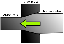
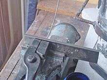
The wire drawing process is quite simple in concept. The wire is prepared by shrinking the beginning of it, by hammering, filing, rolling or swaging, so that it will fit through the die; the wire is then pulled through the die. As the wire is pulled through the die, its volume remains the same, so as the diameter decreases, the length increases. Usually the wire will require more than one draw, through successively smaller dies, to reach the desired size. The American wire gauge scale is based on this. This can be done on a small scale with a draw plate, or on a large commercial scale using automated machinery.[1][2] The process of wire drawing changes material properties due to cold working.
The area reduction in small wires is generally 15–25% and in larger wires is 20–45%.[1] The exact die sequence for a particular job is a function of area reduction, input wire size and output wire size. As the area reduction changes, so does the die sequence.[3]
Very fine wires are usually drawn in bundles. In a bundle, the wires are separated by a metal with similar properties, but with lower chemical resistance so that it can be removed after drawing. If the reduction in area is greater than 50%, the process may require an intermediate step of annealing before it can be redrawn.
Commercial wire drawing usually starts with a coil of hot rolled 9 mm (0.35 in) diameter wire. The surface is first treated to remove scales. It is then fed into a wire drawing machine which may have one or more blocks in series.
Single block wire drawing machines include means for holding the dies accurately in position and for drawing the wire steadily through the holes. The usual design consists of a cast-iron bench or table having a bracket standing up to hold the die, and a vertical drum which rotates and by coiling the wire around its surface pulls it through the die, the coil of wire being stored upon another drum or "swift" which lies behind the die and reels off the wire as fast as required. The wire drum or "block" is provided with means for rapidly coupling or uncoupling it to its vertical shaft, so that the motion of the wire may be stopped or started instantly. The block is also tapered, so that the coil of wire may be easily slipped off upwards when finished. Before the wire can be attached to the block, a sufficient length of it must be pulled through the die; this is effected by a pair of gripping pincers on the end of a chain which is wound around a revolving drum, so drawing the wire until enough can be coiled two or three times on the block, where the end is secured by a small screw clamp or vice. When the wire is on the block, it is set in motion and the wire is drawn steadily through the die; it is very important that the block rotates evenly and that it runs true and pulls the wire at a constant velocity, otherwise "snatching" occurs which will weaken or even break the wire. The speeds at which wire is drawn vary greatly, according to the material and the amount of reduction.
Machines with continuous blocks differ from single block machines by having a series of dies through which the wire is drawn in a continuous fashion. Due to the elongation and slips, the speed of the wire changes after each successive redraw. This increased speed is accommodated by having a different rotation speed for each block. One of these machines may contain 3 to 12 dies.[2] The operation of threading the wire through all the dies and around the blocks is termed "stringing-up". The arrangements for lubrication include a pump which floods the dies, and in many cases also the bottom portions of the blocks run in lubricant.[4]
Often intermediate anneals are required to counter the effects of cold working, and to allow more further drawing. A final anneal may also be used on the finished product to maximize ductility and electrical conductivity.[5]
An example of product produced in a continuous wire drawing machine is telephone wire. It is drawn 20 to 30 times from hot rolled rod stock.[2]
While round cross-sections dominate most drawing processes, non-circular cross-sections are drawn. They are usually drawn when the cross-section is small and quantities are too low to justify rolling. In these processes, a block or Turk's-head machine are used.[6]
Lubrication
Lubrication in the drawing process is essential for maintaining good surface finish and long die life. The following are different methods of lubrication:[1]
- Wet drawing: the dies and wire or rod are completely immersed in lubricants
- Dry drawing: the wire or rod passes through a container of lubricant which coats the surface of the wire or rod
- Metal coating: the wire or rod is coated with a soft metal which acts as a solid lubricant
- Ultrasonic vibration: the dies and mandrels are vibrated, which helps to reduce forces and allow larger reductions per pass
- Roller die Drawing (also referred as Roll drawing): roller dies are used instead of fixed dies to convert shear friction to rolling friction with dramatic reduction in the drawing forces as reported by Lambiase.[7][8][9] When roller dies are adopted, the drawing stages are composed by 2-4 idle rolls and the wire is pulled within the rolls clearance. This type of solution can be easily adopted also to produce flat or profiled drawn wires.
Various lubricants, such as oil, are employed. Another lubrication method is to immerse the wire in a copper(II) sulfate solution, such that a film of copper is deposited which forms a kind of lubricant. In some classes of wire the copper is left after the final drawing to serve as a preventive of rust or to allow easy soldering.The best example of copper coated wire is in MIG wire used in welding.[10]
Mechanical properties
The strength-enhancing effect of wire drawing can be substantial. The highest strengths available on any steel have been recorded on small-diameter cold-drawn austenitic stainless wire. Tensile strength can be as high as 400 ksi (2760 MPa).[11]
Drawing dies

Drawing dies are typically made of tool steel, tungsten carbide, or diamond, with tungsten carbide and manufactured diamond being the most common.[2] For drawing very fine wire a single crystal diamond die is used.[2] For hot drawing, cast-steel dies are used. For steel wire drawing, a tungsten carbide die is used. The dies are placed in a steel casing, which backs the die and allow for easy die changes.[2] Die angles usually range from 6–15°, and each die has at least 2 different angles: the entering angle and approach angle.[2]
See also
References
Notes
- 1 2 3 4 Kalpakjian, pp. 415–419.
- 1 2 3 4 5 6 7 Degarmo, p. 434.
- ↑ Die sequence calculations for wire drawing dies
- ↑
 Chisholm, Hugh, ed. (1911). "Wire". Encyclopædia Britannica. 28 (11th ed.). Cambridge University Press. p. 738.
 - ↑ Degarmo, p. 435.
- ↑ Davis, Joseph R; Handbook Committee, ASM International (2001-08-01). "Copper and copper alloys". ISBN 978-0-87170-726-0.
- ↑ Lambiase, F.; Di Ilio, A. (2011). "A parametric study on residual stresses and loads in drawing process with idle rolls". Materials & Design. 32 (10): 4832–4838. doi:10.1016/j.matdes.2011.06.019.
- ↑ Lambiase, F.; Di Ilio, A. (2012). "Experimental and Finite Element Investigation of Roll Drawing Process". Journal of Materials Engineering and Performance. 21 (2): 161–166. doi:10.1007/s11665-011-9932-1.
- ↑ Lambiase, F.; Di Ilio, A. (2012). "Deformation inhomogeneity in roll drawing process". Journal of Manufacturing Processes. 14 (3): 208–215. doi:10.1016/j.jmapro.2011.12.005.
- ↑ Mig Wire Properties
- ↑ Budinski, p. 430
Bibliography
- Budinski, Kenneth G. (1996). Engineering Materials: Properties and Selection (5th ed.). Upper Saddle River, NJ: Prentice-Hall, Inc. ISBN 0-13-367715-X.
- Degarmo, E. Paul; Black, J T.; Kohser, Ronald A. (2003). Materials and Processes in Manufacturing (9th ed.). Wiley. ISBN 0-471-65653-4..
- Kalpakjian, Serope; Schmid, Steven R. (2006). Manufacturing Engineering and Technology (5th ed.). Upper Saddle River, NJ: Pearson Prentice Hall. p. 429. ISBN 0-13-148965-8.