Waveguide


A waveguide is a structure that guides waves, such as electromagnetic waves or sound waves. They enable a signal to propagate with minimal loss of energy by restricting expansion to one dimension or two. This is a similar effect to waves of water constrained within a canal, or why guns have barrels that restrict hot gas expansion to maximize energy transfer to their bullets. Without the physical constraint of a waveguide, signals will typically be radiated and decreased according to the inverse square law as they expand into three dimensional space.
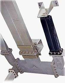
There are different types of waveguides for each type of wave. The original and most common[1] meaning is a hollow conductive metal pipe used to carry high frequency radio waves, particularly microwaves.
The geometry of a waveguide reflects its function. Slab waveguides confine energy to travel only in one dimension, fiber or channel waveguides for two dimensions. The frequency of the transmitted wave also dictates the shape of a waveguide: an optical fiber guiding high-frequency light will not guide microwaves of a much lower frequency. As a rule of thumb, the width of a waveguide needs to be of the same order of magnitude as the wavelength of the guided wave.
Some naturally occurring structures can also act as waveguides. The SOFAR channel layer in the ocean can guide the sound of whale song across enormous distances.[2]
Principle of operation

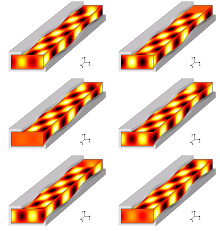
Waves propagate in all directions in open space as spherical waves. The power of the wave falls with the distance R from the source as the square of the distance (inverse square law). A waveguide confines the wave to propagate in one dimension, so that, under ideal conditions, the wave loses no power while propagating. Due to total reflection at the walls, waves are confined to the interior of a waveguide. The propagation inside the waveguide, hence, can be described approximately as a "zigzag" between the walls. This description is exact for electromagnetic waves in a hollow metal tube with a rectangular or circular cross-section.
History
The first structure for guiding waves was proposed by J. J. Thomson in 1893, and was first experimentally tested by Oliver Lodge in 1894. The first mathematical analysis of electromagnetic waves in a metal cylinder was performed by Lord Rayleigh in 1897.[3] For sound waves, Lord Rayleigh published a full mathematical analysis of propagation modes in his seminal work, “The Theory of Sound”.[4]
The study of dielectric waveguides (such as optical fibers, see below) began as early as the 1920s, by several people, most famous of which are Rayleigh, Sommerfeld and Debye.[5] Optical fiber began to receive special attention in the 1960s due to its importance to the communications industry.
Uses

The uses of waveguides for transmitting signals were known even before the term was coined. The phenomenon of sound waves guided through a taut wire have been known for a long time, as well as sound through a hollow pipe such as a cave or medical stethoscope. Other uses of waveguides are in transmitting power between the components of a system such as radio, radar or optical devices. Waveguides are the fundamental principle of guided wave testing (GWT), one of the many methods of non-destructive evaluation.
Specific examples:
- Optical fibers transmit light and signals for long distances and with a high signal rate.
- In a microwave oven a waveguide transfers power from the magnetron, where waves are formed, to the cooking chamber.
- In a radar, a waveguide transfers radio frequency energy to and from the antenna, where the impedance needs to be matched for efficient power transmission (see below).
- A waveguide called a stripline can be created on a printed circuit board, and is used to transmit microwave signals on the board. This type of waveguide is very cheap to manufacture and has small dimensions which fit inside printed circuit boards.
- Waveguides are used in scientific instruments to measure optical, acoustic and elastic properties of materials and objects. The waveguide can be put in contact with the specimen (as in a medical ultrasonography), in which case the waveguide ensures that the power of the testing wave is conserved, or the specimen may be put inside the waveguide (as in a dielectric constant measurement[6]), so that smaller objects can be tested and the accuracy is better.
Propagation modes and cutoff frequencies
A propagation mode in a waveguide is one solution of the wave equations, or, in other words, the form of the wave.[5] Due to the constraints of the boundary conditions, there are only limited frequencies and forms for the wave function which can propagate in the waveguide. The lowest frequency in which a certain mode can propagate is the cutoff frequency of that mode. The mode with the lowest cutoff frequency is the basic mode of the waveguide, and its cutoff frequency is the waveguide cutoff frequency.
Impedance matching
In circuit theory, the impedance is a generalization of electrical resistivity in the case of alternating current, and is measured in ohms ().[5] A waveguide in circuit theory is described by a transmission line having a length and self-impedance. In other words, the impedance is the resistance of the circuit component (in this case a waveguide) to the propagation of the wave. This description of the waveguide was originally intended for alternating current, but is also suitable for electromagnetic and sound waves, once the wave and material properties (such as pressure, density, dielectric constant) are properly converted into electrical terms (current and impedance for example).
Impedance matching is important when components of an electric circuit are connected (waveguide to antenna for example): The impedance ratio determines how much of the wave is transmitted forward and how much is reflected. In connecting a waveguide to an antenna a complete transmission is usually required, so their impedances are matched.
The reflection coefficient can be calculated using: , where is the reflection coefficient (0 denotes full transmission, 1 full reflection, and 0.5 is a reflection of half the incoming voltage), and are the impedance of the first component (from which the wave enters) and the second component, respectively.
An impedance mismatch creates a reflected wave, which added to the incoming waves creates a standing wave. An impedance mismatch can be also quantified with the standing wave ratio (SWR or VSWR for voltage), which is connected to the impedance ratio and reflection coefficient by: , where are the minimum and maximum values of the voltage absolute value, and the VSWR is the voltage standing wave ratio, which value of 1 denotes full transmission, without reflection and thus no standing wave, while very large values mean high reflection and standing wave pattern.
Electromagnetic waveguides
Waveguides can be constructed to carry waves over a wide portion of the electromagnetic spectrum, but are especially useful in the microwave and optical frequency ranges. Depending on the frequency, they can be constructed from either conductive or dielectric materials. Waveguides are used for transferring both power and communication signals.
Optical waveguides
Waveguides used at optical frequencies are typically dielectric waveguides, structures in which a dielectric material with high permittivity, and thus high index of refraction, is surrounded by a material with lower permittivity. The structure guides optical waves by total internal reflection. An example of an optical waveguide is optical fiber.
Other types of optical waveguide are also used, including photonic-crystal fiber, which guides waves by any of several distinct mechanisms. Guides in the form of a hollow tube with a highly reflective inner surface have also been used as light pipes for illumination applications. The inner surfaces may be polished metal, or may be covered with a multilayer film that guides light by Bragg reflection (this is a special case of a photonic-crystal fiber). One can also use small prisms around the pipe which reflect light via total internal reflection —such confinement is necessarily imperfect, however, since total internal reflection can never truly guide light within a lower-index core (in the prism case, some light leaks out at the prism corners).
Acoustic waveguides
An acoustic waveguide is a physical structure for guiding sound waves. A duct for sound propagation also behaves like a transmission line. The duct contains some medium, such as air, that supports sound propagation. Acoustic waveguides have no cutoff frequency, which is in sharp contrast to electromagnetic waveguides.
Mathematical waveguides
Waveguides are interesting objects of study from a strictly mathematical perspective. A waveguide (or tube) is defined as type of boundary condition on the wave equation such that the wave function must be equal to zero on the boundary and that the allowed region is finite in all dimensions but one (an infinitely long cylinder is an example.) A large number of interesting results can be proven from these general conditions. It turns out that any tube with a bulge (where the width of the tube increases) admits at least one bound state. This can be shown using the variational principles. An interesting result by Jeffrey Goldstone and Robert Jaffe [7] is that any tube of constant width with a twist, admits a bound state.
Sound synthesis
Sound synthesis uses digital delay lines as computational elements to simulate wave propagation in tubes of wind instruments and the vibrating strings of string instruments.
See also
References
- ↑ Institute of Electrical and Electronics Engineers, “The IEEE standard dictionary of electrical and electronics terms”; 6th ed. New York, N.Y., Institute of Electrical and Electronics Engineers, c1997. IEEE Std 100-1996. ISBN 1-55937-833-6 [ed. Standards Coordinating Committee 10, Terms and Definitions; Jane Radatz, (chair)]
- ↑ ORIENTATION BY MEANS OF LONG RANGE ACOUSTIC SIGNALING IN BALEEN WHALES, R. Payne, D. Webb, in Annals NY Acad. Sci., 188:110-41 (1971)
- ↑ N. W. McLachlan, Theory and Applications of Mathieu Functions, p. 8 (1947) (reprinted by Dover: New York, 1964).
- ↑ The Theory of Sound, by J. W. S. Rayleigh, (1894)
- 1 2 3 Advanced Engineering Electromagnetics, by C. A. Balanis, John Wiley & Sons (1989).
- ↑ J. R. Baker-Jarvis, "Transmission / reflection and short-circuit line permittivity measurements", NIST tech. note 1341, July 1990
- ↑
External links
| Look up waveguide in Wiktionary, the free dictionary. |
| Wikimedia Commons has media related to Waveguides. |
- Waveguide A very basic explanation on what is a waveguide
- Waveguide basics Multiple pages giving detailed tutorial
- Electromagnetic Waves and Antennas: Waveguides Sophocles J. Orfanidis, Department of Electrical and Computer Engineering, Rutgers University
- Bound States in Twisting Tubes, J Goldstone, R.L. Jaffe, MIT Department of Physics