Vertical axis wind turbine


Vertical-axis wind turbines (VAWTs) are a type of wind turbine where the main rotor shaft is set transverse to the wind (but not necessarily vertically) while the main components are located at the base of the turbine. This arrangement allows the generator and gearbox to be located close to the ground, facilitating service and repair. VAWTs do not need to be pointed into the wind,[1][2] which removes the need for wind-sensing and orientation mechanisms. Major drawbacks for the early designs (Savonius, Darrieus and giromill) included the significant torque variation or "ripple" during each revolution, and the large bending moments on the blades. Later designs addressed the torque ripple issue by sweeping the blades helically.
A VAWT tipped sideways, with the axis perpendicular to the wind streamlines, functions similarly. A more general term that includes this option is "transverse axis wind turbine" or "cross-flow wind turbine." For example, the original Darrieus patent, US Patent 1835018, includes both options.
Drag-type VAWTs such as the Savonius rotor typically operate at lower tipspeed ratios than lift-based VAWTs such as Darrieus rotors and cycloturbines.
General aerodynamics
The forces and the velocities acting in a Darrieus turbine are depicted in figure 1. The resultant velocity vector, , is the vectorial sum of the undisturbed upstream air velocity, , and the velocity vector of the advancing blade, .


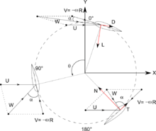

Thus the oncoming fluid velocity varies during each cycle. Maximum velocity is found for and the minimum is found for , where is the azimuthal or orbital blade position. The angle of attack, , is the angle between the oncoming air speed, W, and the blade's chord. The resultant airflow creates a varying, positive angle of attack to the blade in the upstream zone of the machine, switching sign in the downstream zone of the machine.


It follows from geometric considerations of angular velocity as seen in the accompanying figure that:

and:

Solving for the relative velocity as the resultant of the tangential and normal components yields:

Thus, combining the above with the definitions for the tip speed ratio yields the following expression for the resultant velocity:


Angle of attack is solved as:

Which when substituting the above yields:

The resultant aerodynamic force is resolved either into lift (F_L) - drag (D) components or normal (N) - tangential (T) components. The forces are considered acting at the quarter-chord point, and the pitching moment is determined to resolve the aerodynamic forces. The aeronautical terms "lift" and "drag" refer to the forces across (lift) and along (drag) the approaching net relative airflow. The tangential force acts along the blade's velocity, pulling the blade around, and the normal force acts radially, pushing against the shaft bearings. The lift and the drag force are useful when dealing with the aerodynamic forces around the blade such as dynamic stall, boundary layer etc.; while when dealing with global performance, fatigue loads, etc., it is more convenient to have a normal-tangential frame. The lift and the drag coefficients are usually normalised by the dynamic pressure of the relative airflow, while the normal and tangential coefficients are usually normalised by the dynamic pressure of undisturbed upstream fluid velocity.

A = Blade Area (not to be confused with the Swept Area), R = Radius of turbine
The amount of power, P, that can be absorbed by a wind turbine:

Where is the power coefficient, is air density, is the swept area of the turbine, and is the wind speed.[6]


Advantages
VAWTs offer a number of advantages over traditional horizontal-axis wind turbines (HAWTs):
- they are omni-directional and do not need to track the wind. This means they don't require a complex mechanism and motors to yaw the rotor and pitch the blades.
- ability to take advantage of turbulent and gusty winds. Such winds are not harvested by HAWTs, and in fact cause accelerated fatigue for HAWTs.
- the gearbox of a VAWT takes much less fatigue than that of a HAWT. Should it be required, replacement is less costly and simpler, as the gearbox is easily accessible at ground level. This means that a crane or other large equipment is not needed at the site, reducing cost and impact on the environment. Motor and gearbox failures generally increase the operational and maintenance costs of HAWT wind farms both on and offshore.
- some VAWTs (4Navitas) can use a screw pile foundation, allowing a huge reduction in the carbon cost of an installation as well as a reduction in road transport of concrete during installation. They can be fully recycled at the end of their life.
- wings of the Darrieus type have a constant chord and so are easier to manufacture than the blades of a HAWT, which have a much more complex shape and structure.
- can be grouped more closely in wind farms, increasing the generated power per unit of land area.
- can be installed on a wind farm below the existing HAWTs; this will improve the efficiency (power output) of the existing farm.[7]
- research at Caltech has also shown that a carefully designed wind farm using VAWTs can have an output power ten times that of a HAWT wind farm of the same size.[8]
Disadvantages
One of the major outstanding challenges facing vertical axis wind turbine technology is dynamic stall of the blades as the angle of attack varies rapidly.[9][10]
The blades of a VAWT are fatigue-prone due to the wide variation in applied forces during each rotation. This can be overcome by the use of modern composite materials and improvements in design - including the use of aerodynamic wing tips that cause the spreader wing connections to have a static load. The vertically oriented blades can twist and bend during each turn, causing them to break apart.
VAWTs have proven less reliable than HAWTs,[11] although modern designs of VAWTs have overcome many of the issues associated with early designs.[12]
Applications
The Windspire, a small VAWT intended for individual (home or office) use was developed in the early 2000s by US company Mariah Power. The company reported that several units had been installed across the US by June 2008.[13]
Arborwind, an Ann-Arbor (Michigan, US) based company, produces a patented small VAWT which has been installed at several US locations as of 2013.[14]
In 2011, Sandia National Laboratories wind-energy researchers began a five-year study of applying VAWT design technology to offshore wind farms.[15] The researchers stated: "The economics of offshore windpower are different from land-based turbines, due to installation and operational challenges. VAWTs offer three big advantages that could reduce the cost of wind energy: a lower turbine center of gravity; reduced machine complexity; and better scalability to very large sizes. A lower center of gravity means improved stability afloat and lower gravitational fatigue loads. Additionally, the drivetrain on a VAWT is at or near the surface, potentially making maintenance easier and less time-consuming. Fewer parts, lower fatigue loads and simpler maintenance all lead to reduced maintenance costs."
A 24-unit VAWT demonstration plot was installed in southern California in the early 2010s by Caltech aeronautical professor John Dabiri. His design was incorporated in a 10-unit generating farm installed in 2013 in the Alaskan village of Igiugig.[16]
Dulas, Anglesey received permission in March 2014 to install a prototype VAWT on the breakwater at Port Talbot waterside. The turbine is a new design, supplied by Wales-based C-FEC (Swansea),[17] and will be operated for a two-year trial.[18] This VAWT incorporates a wind shield which blocks the wind from the advancing blades, and thus requires a wind-direction sensor and a positioning mechanism, as opposed to the "egg-beater" types of VAWTs discussed above.[17]
4 Navitas (Blackpool) have been operating two prototype VAWTs since June 2013, powered by a Siemens Power Train, they are due to enter the market in January 2015, with a free technology share to interested parties. 4 Navitas are now in the process of scaling their prototype to 1 MW, (working with PERA Technology) and then floating the turbine on an offshore pontoon. This will reduce the cost of offshore wind energy.
The Dynasphere, is Michael Reynolds' (from Earthship fame) 4th generation vertical axis windmill. These windmills have two 1.5 KW generators and can produce electricity at very low speeds.[19]
See also
References
- ↑ Jha, Ph.D., A.R. (2010). Wind turbine technology. Boca Raton, FL: CRC Press
- ↑ Marco Raciti Castelli, A. Englaro, Ernesto Benini, The Darrieus wind turbine: Proposal for a new performance prediction model based on CFD, 2011, Energy, volume 36, issue 8, pp 4919-4934 http://www.sciencedirect.com/science/article/pii/S0360544211003616
- ↑ http://www.sciencedirect.com/science/article/pii/S136403210600164X
- ↑ https://fenix.tecnico.ulisboa.pt/downloadFile/395143097660/Extended%20abstract.pdf
- ↑ Amina El Kasmi; Christian Masson, An extended k-epsilon model for turbulent flow through horizontal-axis wind turbines, Journal of Wind Engineering and Industrial Aerodynamics, Volume 96, Issue 1, January 2008, Pages 103-122, retrieved 2010-04-26
- ↑ Sandra Eriksson; Hans Bernhoff; Mats Leijon (June 2008), "Evaluation of different turbine concepts for wind power", Renewable and Sustainable Energy Reviews, 12 (5): 1419–1434, doi:10.1016/j.rser.2006.05.01, ISSN 1364-0321, retrieved 2010-04-26
- ↑ Steven Peace, Another Approach to Wind, retrieved 2010-04-26
- ↑ Kathy Svitil, Wind-turbine placement produces tenfold power increase, researchers say, retrieved 2012-07-31
- ↑ Buchner, A. J.; Lohry, M. W.; Martinelli, L.; Soria, J.; Smits, A. J. (2015). "Dynamic stall in vertical axis wind turbines: Comparing experiments and computations". Journal of Wind Engineering and Industrial Technology. Retrieved 1 October 2015.
- ↑ Ferreira, C. S.; van Kuik, G.; van Bussel, G.; Scarano, F. (2009). "Visualization by PIV of dynamic stall on a vertical axis wind turbine". Experiments in Fluids. Retrieved 1 October 2015.
- ↑ Chiras, D. (2010). Wind power basics: a green energy guide. Gabriola Island, BC, Canada: New Society Pub.
- ↑ Sutherland, Herbert J; Berg, Dale E; Ashwill, Thomas D. (2012). "A Retrospective of VAWT Technology" (PDF). Sandia National Laboratories. Retrieved 19 September 2014.
- ↑ LaMonica, Martin (2 June 2008). "Vertical-axis wind turbine spins into business". CNET. Retrieved 18 September 2015.
- ↑ "History". Arbor Wind. Retrieved 18 September 2015.
- ↑ Holinka, Stephanie (8 August 2012). "Offshore Use of Vertical-axis Wind Turbines Gets Closer Look". Renewable Energy World. Retrieved 18 September 2015.
- ↑ Bullis, Kevin (8 April 2013). "Will Vertical Turbines Make More of the Wind?". MIT Technology Review. Retrieved 18 September 2015.
- 1 2 "C-Fec turbine". C-Fec. Retrieved 18 September 2015.
- ↑ "Dulas secures consent for prototype 'vertical axis' wind turbine". Renewable Energy Focus. 5 March 2014. Retrieved 18 September 2015.
- ↑ "Vertical Axis Wind Power Generation Prototype". Earthship Biotecture. Retrieved 18 September 2015.
External links
| Wikimedia Commons has media related to Vertical-axis wind turbines. |
- Cellar Image of the Day Shows a VAWT transverse to the wind, yet with the axis horizontal, but such does not allow the machine to be called a HAWT.
| Wind power | ||
|---|---|---|
| Wind turbines | ||
| Wind power industry | ||
| Wind farms | ||
| Concepts | ||