Vapor-compression refrigeration
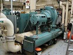
Vapor-Compression Refrigeration or vapor-compression refrigeration system (VCRS),[1] in which the refrigerant undergoes phase changes, is one of the many refrigeration cycles and is the most widely used method for air-conditioning of buildings and automobiles. It is also used in domestic and commercial refrigerators, large-scale warehouses for chilled or frozen storage of foods and meats, refrigerated trucks and railroad cars, and a host of other commercial and industrial services. Oil refineries, petrochemical and chemical processing plants, and natural gas processing plants are among the many types of industrial plants that often utilize large vapor-compression refrigeration systems.
Refrigeration may be defined as lowering the temperature of an enclosed space by removing heat from that space and transferring it elsewhere. A device that performs this function may also be called an air conditioner, refrigerator, air source heat pump, geothermal heat pump or chiller (heat pump).
Description of the vapour-compression refrigeration system
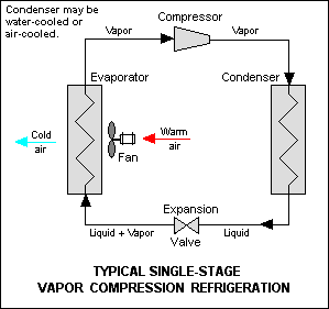
The vapor-compression uses a circulating liquid refrigerant as the medium which absorbs and removes heat from the space to be cooled and subsequently rejects that heat elsewhere. Figure 1 depicts a typical, single-stage vapor-compression system. All such systems have four components: a compressor, a condenser, a thermal expansion valve (also called a throttle valve or metering device), and an evaporator. Circulating refrigerant enters the compressor in the thermodynamic state known as a saturated vapor[2] and is compressed to a higher pressure, resulting in a higher temperature as well. The hot, compressed vapor is then in the thermodynamic state known as a superheated vapor and it is at a temperature and pressure at which it can be condensed with either cooling water or cooling air flowing across the coil or tubes. This is where the circulating refrigerant rejects heat from the system and the rejected heat is carried away by either the water or the air (whichever may be the case).
The condensed liquid refrigerant, in the thermodynamic state known as a saturated liquid, is next routed through an expansion valve where it undergoes an abrupt reduction in pressure. That pressure reduction results in the adiabatic flash evaporation of a part of the liquid refrigerant. The auto-refrigeration effect of the adiabatic flash evaporation lowers the temperature of the liquid and vapor refrigerant mixture to where it is colder than the temperature of the enclosed space to be refrigerated.
The cold mixture is then routed through the coil or tubes in the evaporator. A fan circulates the warm air in the enclosed space across the coil or tubes carrying the cold refrigerant liquid and vapor mixture. That warm air evaporates the liquid part of the cold refrigerant mixture. At the same time, the circulating air is cooled and thus lowers the temperature of the enclosed space to the desired temperature. The evaporator is where the circulating refrigerant absorbs and removes heat which is subsequently rejected in the condenser and transferred elsewhere by the water or air used in the condenser.
To complete the refrigeration cycle, the refrigerant vapor from the evaporator is again a saturated vapor and is routed back into the compressor.
Refrigerants
"Freon" is a trade name for a family of haloalkane refrigerants manufactured by DuPont and other companies. These refrigerants were commonly used due to their superior stability and safety properties: they were not flammable at room temperature and atmospheric pressure, nor obviously toxic as were the fluids they replaced, such as sulfur dioxide. Haloalkanes are also an order(s) of magnitude more expensive than petroleum derived flammable alkanes of similar or better cooling performance.
Unfortunately, chlorine- and fluorine-bearing refrigerants reach the upper atmosphere when they escape. In the stratosphere, CFCs break up due to UV radiation, releasing their chlorine free radicals. These chlorine free radicals act as catalysts in the breakdown of ozone through chain reactions. One CFC molecule can cause thousands of ozone molecules to break down. This causes severe damage to the ozone layer that shields the Earth's surface from the Sun's strong UV radiation, and has been shown to lead to increased rates of skin cancer. The chlorine will remain active as a catalyst until and unless it binds with another particle, forming a stable molecule. CFC refrigerants in common but receding usage include R-11 and R-12.
Newer refrigerants with reduced ozone depletion effect such as HCFCs (R-22, used in most homes today) and HFCs (R-134a, used in most cars) have replaced most CFC use. HCFCs in turn are being phased out under the Montreal Protocol and replaced by hydrofluorocarbons (HFCs), such as R-410A, which lack chlorine. However, CFCs, HCFCs, and HFCs all have large global warming potential.
More benign refrigerants are currently the subject of research, such as supercritical carbon dioxide, known as R-744.[3] These have similar efficiencies compared to existing CFC and HFC based compounds, and have many orders of magnitude lower global warming potential.
Thermodynamic analysis of the system

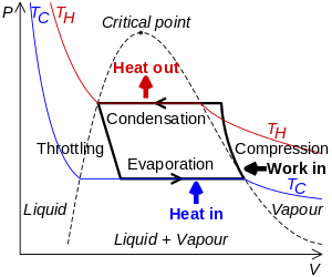
The thermodynamics of the vapor compression cycle can be analyzed on a temperature versus entropy diagram as depicted in Figure 2. At point 1 in the diagram, the circulating refrigerant enters the compressor as a saturated vapor. From point 1 to point 2, the vapor is isentropically compressed (i.e., compressed at constant entropy) and exits the compressor as a superheated vapor.
From point 2 to point 3, the vapor travels through part of the condenser which removes the superheat by cooling the vapor. Between point 3 and point 4, the vapor travels through the remainder of the condenser and is condensed into a saturated liquid. The condensation process occurs at essentially constant pressure.
Between points 4 and 5, the saturated liquid refrigerant passes through the expansion valve and undergoes an abrupt decrease of pressure. That process results in the adiabatic flash evaporation and auto-refrigeration of a portion of the liquid (typically, less than half of the liquid flashes). The adiabatic flash evaporation process is isenthalpic (i.e., occurs at constant enthalpy).
Between points 5 and 1, the cold and partially vaporized refrigerant travels through the coil or tubes in the evaporator where it is totally vaporized by the warm air (from the space being refrigerated) that a fan circulates across the coil or tubes in the evaporator. The evaporator operates at essentially constant pressure and boils off all available liquid there after adding 4-8 deg kelvin of superheat to the refrigerant as a safeguard for the compressor as it cannot pump liquid. The resulting refrigerant vapor returns to the compressor inlet at point 1 to complete the thermodynamic cycle.
It should be noted that the above discussion is based on the ideal vapor-compression refrigeration cycle which does not take into account real world items like frictional pressure drop in the system, slight internal irreversibility during the compression of the refrigerant vapor, or non-ideal gas behavior (if any).
Types of gas compressors
The most common compressors used in chillers are reciprocating, rotary screw, centrifugal, and scroll compressors. Each application prefers one or another due to size, noise, efficiency and pressure issues. Compressors are often described as being either open, hermetic, or semi-hermetic, to describe how the compressor and/or motor is situated in relation to the refrigerant being compressed. Variations of motor/compressor types can lead to the following configurations:
- Hermetic motor, hermetic compressor
- Hermetic motor, semi-hermetic compressor
- Open motor (belt driven or close coupled), hermetic compressor
- Open motor (belt driven or close coupled), semi-hermetic compressor
Typically in hermetic, and most semi-hermetic compressors (sometimes known as accessible hermetic compressors), the compressor and motor driving the compressor are integrated, and operate within the refrigerant system. The motor is hermetic and is designed to operate, and be cooled by, the refrigerant being compressed. The obvious disadvantage of hermetic motor compressors is that the motor drive cannot be maintained in situ, and the entire compressor must be removed if a motor fails. A further disadvantage is that burnt out windings can contaminate whole refrigeration systems requiring the system to be entirely pumped down and the refrigerant replaced.
An open compressor has a motor drive which is outside of the refrigeration system, and provides drive to the compressor by means of an input shaft with suitable gland seals. Open compressor motors are typically air-cooled and can be fairly easily exchanged or repaired without degassing of the refrigeration system. The disadvantage of this type of compressor is a failure of the shaft seals, leading to loss of refrigerant.
Open motor compressors are generally easier to cool (using ambient air) and therefore tend to be simpler in design and more reliable, especially in high pressure applications where compressed gas temperatures can be very high. However the use of liquid injection for additional cooling can generally overcome this issue in most hermetic motor compressors.
Reciprocating compressors

Reciprocating compressors are piston-style, positive displacement compressors.
Rotary screw compressors

screw compressor
Rotary screw compressors are also positive displacement compressors. Two meshing screw-rotors rotate in opposite directions, trapping refrigerant vapor, and reducing the volume of the refrigerant along the rotors to the discharge point.
Centrifugal compressors
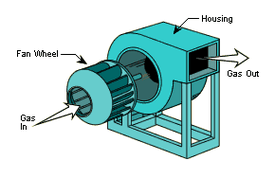
Centrifugal compressors are dynamic compressors. These compressors raise the pressure of the refrigerant by imparting velocity or dynamic energy, using a rotating impeller, and converting it to pressure energy.
Scroll compressors

Scroll compressors are also positive displacement compressors. The refrigerant is compressed when one spiral orbits around a second stationary spiral, creating smaller and smaller pockets and higher pressures. By the time the refrigerant is discharged, it is fully pressurized.
Others
 Diaphragm pump
 Axial-flow compressor
 mixed-flow compressor
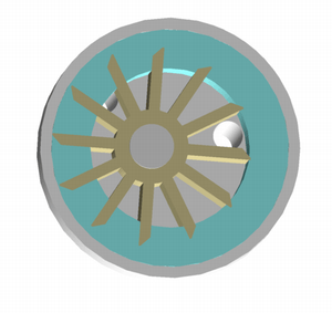 Liquid ring
 Roots blower
Compressor lubrication
In order to lubricate the moving parts of the compressor, oil is added to the refrigerant during installation or commissioning. The type of oil may be mineral or synthetic to suit the compressor type, and also chosen so as not to react with the refrigerant type and other components in the system. In small refrigeration systems the oil is allowed to circulate throughout the whole circuit, but care must be taken to design the pipework and components such that oil can drain back under gravity to the compressor. In larger more distributed systems, especially in retail refrigeration, the oil is normally captured at an oil separator immediately after the compressor, and is in turn re-delivered, by an oil level management system, back to the compressor(s). Oil separators are not 100% efficient so system pipework must still be designed so that oil can drain back by gravity to the oil separator or compressor.
Some newer compressor technologies use magnetic bearings and require no lubrication, for example the Danfoss Turbocor range of centrifugal compressors. Avoiding the need for oil lubrication and the design requirements and ancillaries associated with it, simplifies the design of the refrigerant system and reduces maintenance requirements.
Control
In simple commercial refrigeration systems the compressor is normally controlled by a simple pressure switch, with the expansion performed by a capillary tube or simple thermostatic expansion valve. In more complex systems, including multiple compressor installations, the use of electronic controls is typical, with adjustable set points to control the pressure at which compressors cut in and cut out, and temperature control by the use of electronic expansion valves.
In addition to the operational controls, separate high pressure and low pressure switches are normally utilised to provide secondary protection to the compressors and other components of the system from operating outside of safe parameters.
In more advanced electronic control systems the use of floating head pressure, and proactive suction pressure, control routines allow the compressor operation to be adjusted to accurately meet differing cooling demands whilst reducing energy consumption.
Other features and facts of interest
The schematic diagram of a single-stage refrigeration system shown in Figure 1 does not include other equipment items that would be provided in a large commercial or industrial vapor compression refrigeration system, such as:
- A horizontal or vertical pressure vessel, equipped internally with a demister, between the evaporator and the compressor inlet to capture and remove any residual, entrained liquid in the refrigerant vapor because liquid may damage the compressor. Such vapor-liquid separators are most often referred to as "suction line accumulators". (In other industrial processes, they are called "compressor suction drums" or "knockout pots".)
- Large commercial or industrial refrigeration systems may have multiple expansion valves and multiple evaporators in order to refrigerate multiple enclosed spaces or rooms. In such systems, the condensed liquid refrigerant may be routed into a pressure vessel, called a receiver, from which liquid refrigerant is withdrawn and routed through multiple pipelines to the multiple expansion valves and evaporators.
- Filter Dryers, installed before the compressors to catch any moisture or contaminants in the system and thus protect the compressors from internal damage
- Some refrigeration units may have multiple stages which requires the use of multiple compressors in various arrangements.[4]
The cooling capacity of refrigeration systems is often defined in units called "tons of refrigeration". The most common definition of that unit is: 1 ton of refrigeration is the rate of heat removal required to freeze a short ton (i.e., 2000 pounds, 907.2 kg) of water at 32 °F (0 ⁰C) in 24 hours. Based on the heat of fusion for water being 144 Btu per pound, 1 ton of refrigeration = 12,000 Btu/h = 12,660 kJ/h = 3.517 kW. Most residential air conditioning units range in capacity from about 1 to 5 tons (3.5 - 18 kW) of refrigeration.
A much less common definition is: 1 tonne of refrigeration is the rate of heat removal required to freeze a metric ton (i.e., 1000 kg) of water at 0 °C in 24 hours. Based on the heat of fusion being 334.9 kJ/kg, 1 tonne of refrigeration = 13,954 kJ/h = 3.876 kW. As can be seen, the definition of 1 tonne of refrigeration in metric units is 10 percent larger than 1 ton of refrigeration using old imperial units.
Applications
| Refrigeration application | Short descriptions | Typical refrigerants used |
|---|---|---|
| Domestic refrigeration | Appliances used for keeping food in dwelling units | R-600a, R-134a, R-22, |
| Commercial refrigeration | Holding and displaying frozen and fresh food in retail outlets | R-134a, R-404A, R-507 |
| Food processing and cold storage | Equipment to preserve, process and store food from its source to the wholesale distribution point | R-123, R-134a, R-407C, R-410A, R-507 |
| Industrial refrigeration | Large equipment, typically 25 kW to 30 MW, used for chemical processing, cold storage, food processing, building and district heating and cooling | R-123, R-134a, R-404A, R-407C, R-507, R-717 |
| Transport refrigeration | Equipment to preserve and store goods, primarily foodstuffs, during transport by road, rail, air and sea | R-134a, R-407C, R-410A |
| Electronic cooling | Low-temperature cooling of CMOS circuitry and other components in large computers and servers[5] | R-134a, R-404A, R-507 |
| Medical refrigeration | R-134a, R-404A, R-507 | |
| Cryogenic refrigeration | Ethylene, Propane, Nitrogen, Helium |
Economic analysis
Advantages
- Very mature technology.
- Relatively inexpensive.
- Can be driven directly using mechanical energy (water, car/truck motor) or with electrical energy.
- Efficient up to 60% of Carnot's theoretical limit (as evaluated in ASHRAE testing conditions: evaporation temperature of -23.3 °C, condensing temperature of 54.4 °C, and ambient temperature of 32 °C) based on some of the best commercially available compressors, as produced by manufacturers Danfoss, Matsushita, Copeland, Embraco, Bristol and Tecumseh. However, many refrigeration systems use compressors that have lower efficiencies of between 40-55%, since the 60% efficient ones cost almost twice as much as the lower efficiency ones.
Disadvantages
Many systems still use HCFC refrigerants, which contribute to depletion of the Earth's ozone layer. In countries adhering to the Montreal Protocol, HCFCs are due to be phased out and are largely being replaced by ozone-friendly HFCs. However, systems using HFC refrigerants tend to be slightly less efficient than systems using HCFCs. HFCs also have an extremely large global warming potential, because they remain in the atmosphere for many years and trap heat more effectively than carbon dioxide.
With the ultimate phasing out of HCFCs already a certainty, alternative non-haloalkane refrigerants are gaining popularity. In particular, once-abandoned refrigerants such as hydrocarbons (butane for example) and CO2 are coming back into more extensive use. For example, Coca-Cola's vending machines at the 2006 FIFA World Cup in Germany used refrigeration utilizing CO2.[6] Ammonia (NH3) is one of the oldest refrigerants, with excellent performance and essentially no pollution problems. However, ammonia has two disadvantages: it is toxic and it is incompatible with copper tubing.[7]
History
In 1805, the American inventor Oliver Evans described a closed vapor-compression refrigeration cycle for the production of ice by ether under vacuum. Heat would be removed from the environment by recycling vaporized refrigerant, where it would move through a compressor and condenser and would eventually revert to a liquid form in order to repeat the refrigeration process over again. However, no such refrigeration unit was built by Evans.[8]
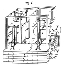
In 1834, an American expatriate to Great Britain, Jacob Perkins, built the first working vapor-compression refrigeration system in the world.[9] It was a closed-cycle that could operate continuously, as he described in his patent:
- I am enabled to use volatile fluids for the purpose of producing the cooling or freezing of fluids, and yet at the same time constantly condensing such volatile fluids, and bringing them again into operation without waste.
His prototype system worked although it did not succeed commercially.[10]
A similar attempt was made in 1842, by American physician, John Gorrie,[11] who built a working prototype, but it was a commercial failure. American engineer Alexander Twining took out a British patent in 1850 for a vapour compression system that used ether.
The first practical vapor compression refrigeration system was built by James Harrison, a British journalist who had emigrated to Australia.[12] His 1856 patent was for a vapour compression system using ether, alcohol or ammonia. He built a mechanical ice-making machine in 1851 on the banks of the Barwon River at Rocky Point in Geelong, Victoria, and his first commercial ice-making machine followed in 1854. Harrison also introduced commercial vapour-compression refrigeration to breweries and meat packing houses, and by 1861, a dozen of his systems were in operation in Australia and England.
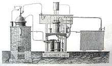
The first gas absorption refrigeration system using gaseous ammonia dissolved in water (referred to as "aqua ammonia") was developed by Ferdinand Carré of France in 1859 and patented in 1860. Carl von Linde, an engineering professor at the Technological University Munich in Germany, patented an improved method of liquefying gases in 1876. His new process made possible using gases such as ammonia, sulfur dioxide (SO2) and methyl chloride (CH3Cl) as refrigerants and they were widely used for that purpose until the late 1920s.
See also
- Absorption refrigeration or Einstein refrigerator or Gas absorption refrigerator
- Air conditioning
- Flash evaporation
- Heat pump
- HVAC - heating, ventilation, and air conditioning
- Magnetic refrigeration
- Refrigeration
- Refrigeration cycle
- Phase diagram - diagram over solid-liquid-gas vs pressure-temperature
References
- ↑ Y.V.C. Rao (2003). An Introduction to Thermodynamics (2nd ed.). Universities Press. ISBN 978-81-7371-461-0.
- ↑ Saturated vapors and saturated liquids are vapors and liquids at their saturation temperature and saturation pressure.HELL YEAH PEOPLE A superheated vapor is at a temperature higher than the saturation temperature corresponding to its pressure.
- ↑ r744.com - Everything R744, The Natural Refrigerant R744 (CO)2, 2006-2012
- ↑ Vapor-Compression Refrigeration Cycles, Schematic diagrams of multi-stage units, Southern Illinois University Carbondale, 1998-11-30
- ↑ Schmidt, R.R. and Notohardjono, B.D. (2002), "High-end server low-temperature cooling", IBM Journal of Research and Development, Vol. 46, Issue 6, pp.739-751.
- ↑ 2006 Environmental Performance, the Coca-Cola Company (scroll down to pdf page 6 of 9 pdf pages).
- ↑ osha.gov - Ammonia Refrigeration - Properties of Ammonia, 2011
- ↑ Colin Hempstead and William E. Worthington (Editors) (2005). Encyclopedia of 20th-Century Technology, Volume 2. Taylor& Francis. ISBN 1-57958-464-0.
- ↑ Robert T. Balmer (2011). Modern Engineering Thermodynamic. Academic Press. ISBN 978-0-12-374996-3.
- ↑ Burstall, Aubrey F. (1965). A History of Mechanical Engineering. The MIT Press. ISBN 0-262-52001-X.
- ↑ "Improved process for the artificial production of ice", U.S. Patent Office, Patent 8080, 1851
- ↑ "Harrison Refrigerator Model".
Further reading
- Yunus A. Cengel and Michael A. Boles (2008). Thermodynamics: An Engineering Approach (6th ed.). McGraw-Hill. ISBN 0-07-352921-4.
External links
- "The ideal vapor compression refrigeration cycle", University of Nevada (US)
- "The Refrigeration Cycle: Central Air Conditioner For Homeowners"
- "The Refrigeration Cycle", from HowStuffWorks
- Scientific papers about CO2 heat pumps / refrigeration