Schlegel diagram

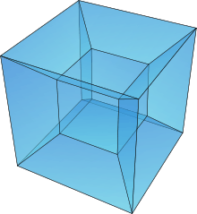


In geometry, a Schlegel diagram is a projection of a polytope from into through a point beyond one of its facets or faces. The resulting entity is a polytopal subdivision of the facet in that is combinatorially equivalent to the original polytope. Named for Victor Schlegel, who in 1886 introduced this tool for studying combinatorial and topological properties of polytopes. In dimensions 3 and 4, a Schlegel diagram is a projection of a polyhedron into a plane figure and a projection of a 4-polytope to 3-space, respectively. As such, Schlegel diagrams are commonly used as a means of visualizing four-dimensional polytopes.


Construction
The most elementary Schlegel diagram, that of a polyhedron, was described by Duncan Sommerville as follows:[1]
- A very useful method of representing a convex polyhedron is by plane projection. If it is projected from any external point, since each ray cuts it twice, it will be represented by a polygonal area divided twice over into polygons. It is always possible by suitable choice of the centre of projection to make the projection of one face completely contain the projections of all the other faces. This is called a Schlegel diagram of the polyhedron. The Schlegel diagram completely represents the morphology of the polyhedron. It is sometimes convenient to project the polyhedron from a vertex; this vertex is projected to infinity and does not appear in the diagram, the edges through it are represented by lines drawn outwards.
Sommerville also considers the case of a simplex in four dimensions:[2] "The Schlegel diagram of simplex in S4 is a tetrahedron divided into four tetrahedra." More generally, a polytope in n-dimensions has a Schegel diagram constructed by a perspective projection viewed from a point outside of the polytope, above the center of a facet. All vertices and edges of the polytope are projected onto a hyperplane of that facet. If the polytope is convex, a point near the facet will exist which maps the facet outside, and all other facets inside, so no edges need to cross in the projection.
Examples
| Dodecahedron | Dodecaplex |
|---|---|
 12 pentagon faces in the plane |
 120 dodecahedral cells in 3-space |
See also
- Net (polyhedron) – A different approach for visualization by lowering the dimension of a polytope is to build a net, disconnecting facets, and unfolding until the facets can exist on a single hyperplane. This maintains the geometric scale and shape, but makes the topological connections harder to see.
References
- ↑ Duncan Sommerville (1929). Introduction to the Geometry of N Dimensions, p.100. E. P. Dutton. Reprint 1958 by Dover Books.
- ↑ Sommerville (1929), p.101.
Further reading
- Victor Schlegel (1883) Theorie der homogen zusammengesetzten Raumgebilde, Nova Acta, Ksl. Leop.-Carol. Deutsche Akademie der Naturforscher, Band XLIV, Nr. 4, Druck von E. Blochmann & Sohn in Dresden.
- Victor Schlegel (1886) Ueber Projectionsmodelle der regelmässigen vier-dimensionalen Körper, Waren.
- Coxeter, H.S.M.; Regular Polytopes, (Methuen and Co., 1948). (p. 242)
- Regular Polytopes, (3rd edition, 1973), Dover edition, ISBN 0-486-61480-8
- Grünbaum, Branko (2003), Kaibel, Volker; Klee, Victor; Ziegler, Günter M., eds., Convex polytopes (2nd ed.), New York & London: Springer-Verlag, ISBN 0-387-00424-6.
External links
| Wikimedia Commons has media related to Schlegel diagrams. |
- George W. Hart: 4D Polytope Projection Models by 3D Printing
- Nrich maths – for the teenager. Also useful for teachers.