Pinhole camera model
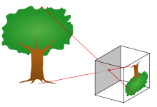
The pinhole camera model describes the mathematical relationship between the coordinates of a 3D point and its projection onto the image plane of an ideal pinhole camera, where the camera aperture is described as a point and no lenses are used to focus light. The model does not include, for example, geometric distortions or blurring of unfocused objects caused by lenses and finite sized apertures. It also does not take into account that most practical cameras have only discrete image coordinates. This means that the pinhole camera model can only be used as a first order approximation of the mapping from a 3D scene to a 2D image. Its validity depends on the quality of the camera and, in general, decreases from the center of the image to the edges as lens distortion effects increase.
Some of the effects that the pinhole camera model does not take into account can be compensated;, for example by applying suitable coordinate transformations on the image coordinates, and other effects are sufficiently small to be neglected if a high quality camera is used. This means that the pinhole camera model often can be used as a reasonable description of how a camera depicts a 3D scene, for example in computer vision and computer graphics.
The geometry and mathematics of the pinhole camera
NOTE: The x1x2x3 coordinate system in the figure is left-handed, that is the direction of the OZ axis is in reverse to the system the reader may be used to.
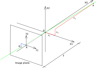
The geometry related to the mapping of a pinhole camera is illustrated in the figure. The figure contains the following basic objects:
- A 3D orthogonal coordinate system with its origin at O. This is also where the camera aperture is located. The three axes of the coordinate system are referred to as X1, X2, X3. Axis X3 is pointing in the viewing direction of the camera and is referred to as the optical axis, principal axis, or principal ray. The 3D plane which intersects with axes X1 and X2 is the front side of the camera, or principal plane.
- An image plane where the 3D world is projected through the aperture of the camera. The image plane is parallel to axes X1 and X2 and is located at distance from the origin O in the negative direction of the X3 axis. A practical implementation of a pinhole camera implies that the image plane is located such that it intersects the X3 axis at coordinate -f where f > 0. f is also referred to as the focal length of the pinhole camera.
- A point R at the intersection of the optical axis and the image plane. This point is referred to as the principal point or image center.
- A point P somewhere in the world at coordinate relative to the axes X1,X2,X3.
- The projection line of point P into the camera. This is the green line which passes through point P and the point O.
- The projection of point P onto the image plane, denoted Q. This point is given by the intersection of the projection line (green) and the image plane. In any practical situation we can assume that > 0 which means that the intersection point is well defined.
- There is also a 2D coordinate system in the image plane, with origin at R and with axes Y1 and Y2 which are parallel to X1 and X2, respectively. The coordinates of point Q relative to this coordinate system is .


The pinhole aperture of the camera, through which all projection lines must pass, is assumed to be infinitely small, a point. In the literature this point in 3D space is referred to as the optical (or lens or camera) center.[1]
Next we want to understand how the coordinates of point Q depend on the coordinates of point P. This can be done with the help of the following figure which shows the same scene as the previous figure but now from above, looking down in the negative direction of the X2 axis.
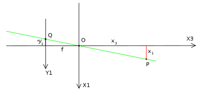
In this figure we see two similar triangles, both having parts of the projection line (green) as their hypotenuses. The catheti of the left triangle are and f and the catheti of the right triangle are and . Since the two triangles are similar it follows that


- or


A similar investigation, looking in the negative direction of the X1 axis gives
- or


This can be summarized as

which is an expression that describes the relation between the 3D coordinates of point P and its image coordinates given by point Q in the image plane.
Rotated image and the virtual image plane
The mapping from 3D to 2D coordinates described by a pinhole camera is a perspective projection followed by a 180° rotation in the image plane. This corresponds to how a real pinhole camera operates; the resulting image is rotated 180° and the relative size of projected objects depends on their distance to the focal point and the overall size of the image depends on the distance f between the image plane and the focal point. In order to produce an unrotated image, which is what we expect from a camera, there are two possibilities:
- Rotate the coordinate system in the image plane 180° (in either direction). This is the way any practical implementation of a pinhole camera would solve the problem; for a photographic camera we rotate the image before looking at it, and for a digital camera we read out the pixels in such an order that it becomes rotated.
- Place the image plane so that it intersects the X3 axis at f instead of at -f and rework the previous calculations. This would generate a virtual (or front) image plane which cannot be implemented in practice, but provides a theoretical camera which may be simpler to analyse than the real one.
In both cases the resulting mapping from 3D coordinates to 2D image coordinates is given by

(same as before except no minus sign)
Homogeneous coordinates
The mapping from 3D coordinates of points in space to 2D image coordinates can also be represented in homogeneous coordinates. Let be a representation of a 3D point in homogeneous coordinates (a 4-dimensional vector), and let be a representation of the image of this point in the pinhole camera (a 3-dimensional vector). Then the following relation holds


where is the camera matrix and the means equality between elements of projective spaces. This implies that the left and right hand sides are equal up to a non-zero scalar multiplication. A consequence of this relation is that also can be seen as an element of a projective space; two camera matrices are equivalent if they are equal up to a scalar multiplication. This description of the pinhole camera mapping, as a linear transformation instead of as a fraction of two linear expressions, makes it possible to simplify many derivations of relations between 3D and 2D coordinates. 123


See also
- Entrance pupil, the equivalent location of the pinhole in relation to object space in a real camera.
- Exit pupil, the equivalent location of the pinhole in relation to the image plane in a real camera.
- Pinhole camera, the practical implementation of the mathematical model described in this article.
References
- ↑ Andrea Fusiello (2005-12-27). "Elements of Geometric Computer Vision". Homepages.inf.ed.ac.uk. Retrieved 2013-12-18.
Bibliography
- David A. Forsyth and Jean Ponce (2003). Computer Vision, A Modern Approach. Prentice Hall. ISBN 0-12-379777-2.
- Richard Hartley and Andrew Zisserman (2003). Multiple View Geometry in computer vision. Cambridge University Press. ISBN 0-521-54051-8.
- Bernd Jähne (1997). Practical Handbook on Image Processing for Scientific Applications. CRC Press. ISBN 0-8493-8906-2.
- Linda G. Shapiro and George C. Stockman (2001). Computer Vision. Prentice Hall. ISBN 0-13-030796-3.
- Gang Xu and Zhengyou Zhang (1996). Epipolar geometry in Stereo, Motion and Object Recognition. Kluwer Academic Publishers. ISBN 0-7923-4199-6.