Passive optical network
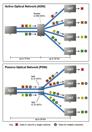
Passive Optical Network (PON) is a telecommunications technology that implements a point-to-multipoint architecture, in which unpowered Fiber Optic Splitters are used to enable a single optical fiber to serve multiple end-points such as customers, without having to provision individual fibers between the hub and customer.
A PON consists of an optical line terminal (OLT) at the service provider's central office (hub) and a number of optical network units (ONUs) or Optical Network Terminals (ONTs), near end users. A PON reduces the amount of fiber and central office equipment required compared with point-to-point architectures. A passive optical network is a form of fiber-optic access network.
In most cases, downstream signals are broadcast to all premises sharing multiple fibers. Encryption can prevent eavesdropping.
Upstream signals are combined using a multiple access protocol, usually time division multiple access (TDMA).
History
Two major standard groups, the Institute of Electrical and Electronics Engineers (IEEE) and the Telecommunication Standardization Sector of the International Telecommunication Union (ITU-T), develop standards along with a number of other industry organizations. The Society of Cable Telecommunications Engineers (SCTE) also specified radio frequency over glass for carrying signals over a passive optical network.
FSAN and ITU
Starting in 1995, work on fiber to the home architectures was done by the Full Service Access Network (FSAN) working group, formed by major telecommunications service providers and system vendors.[1] The International Telecommunications Union (ITU) did further work, and standardized on two generations of PON. The older ITU-T G.983 standard was based on Asynchronous Transfer Mode (ATM), and has therefore been referred to as APON (ATM PON). Further improvements to the original APON standard – as well as the gradual falling out of favor of ATM as a protocol – led to the full, final version of ITU-T G.983 being referred to more often as broadband PON, or BPON. A typical APON/BPON provides 622 megabits per second (Mbit/s) (OC-12) of downstream bandwidth and 155 Mbit/s (OC-3) of upstream traffic, although the standard accommodates higher rates.
The ITU-T G.984 Gigabit-capable Passive Optical Networks (GPON) standard represented an increase, compared to BPON, in both the total bandwidth and bandwidth efficiency through the use of larger, variable-length packets. Again, the standards permit several choices of bit rate, but the industry has converged on 2.488 gigabits per second (Gbit/s) of downstream bandwidth, and 1.244 Gbit/s of upstream bandwidth. GPON Encapsulation Method (GEM) allows very efficient packaging of user traffic with frame segmentation.
By mid-2008, Verizon had installed over 800,000 lines. British Telecom, BSNL, Saudi Telecom Company, Etisalat, and AT&T were in advanced trials in Britain, India, Saudi Arabia, the UAE, and the USA, respectively. GPON networks have now been deployed in numerous networks across the globe, and the trends indicate higher growth in GPON than other PON technologies.
G.987 defined 10G-PON with 10 Gbit/s downstream and 2.5 Gbit/s upstream – framing is "G-PON like" and designed to coexist with GPON devices on the same network.[2]
Security
Developed in 2009 by Cable Manufacturing Business to meet SIPRNet requirements of the US Air Force, secure passive optical network (SPON) integrates gigabit passive optical network (GPON) technology and protective distribution system (PDS).
Changes to the NSTISSI 7003 requirements for PDS and the mandate by the US federal government for GREEN technologies allowed for the US federal government consideration of the two technologies as an alternative to active Ethernet and encryption deviсes.
The chief information officer of the United States Department of the Army issued a directive to adopt the technology by fiscal year 2013. It is marketed to the US military by companies such as Telos Corporation.[3][4][5][6]
IEEE
In 2004, the Ethernet PON (EPON or GEPON) standard 802.3ah-2004 was ratified as part of the Ethernet in the first mile project of the IEEE 802.3. EPON uses standard 802.3 Ethernet frames with symmetric 1 gigabit per second upstream and downstream rates. EPON is applicable for data-centric networks, as well as full-service voice, data and video networks. 10 Gbit/s EPON or 10G-EPON was ratified as an amendment IEEE 802.3av to IEEE 802.3. 10G-EPON supports 10/1 Gbit/s. The downstream wavelength plan support simultaneous operation of 10 Gbit/s on one wavelength and 1 Gbit/s on a separate wavelength for operation of IEEE 802.3av and IEEE 802.3ah on the same PON concurrently. The upstream channel can support simultaneous operation of IEEE 802.3av and 1 Gbit/s 802.3ah simultaneously on a single shared (1310 nm) channel.
There are currently over 40 million installed EPON ports making it the most widely deployed PON technology globally. EPON is also the foundation for cable operators’ business services as part of the DOCSIS Provisioning of EPON (DPoE) specifications.
Network elements
A PON takes advantage of wavelength division multiplexing (WDM), using one wavelength for downstream traffic and another for upstream traffic on a single mode fiber (ITU-T G.652). BPON, EPON, GEPON, and GPON have the same basic wavelength plan and use the 1490 nanometer (nm) wavelength for downstream traffic and 1310 nm wavelength for upstream traffic. 1550 nm is reserved for optional overlay services, typically RF (analog) video.
As with bit rate, the standards describe several optical budgets, most common is 28 dB of loss budget for both BPON and GPON, but products have been announced using less expensive optics as well. 28 dB corresponds to about 20 km with a 32-way split. Forward error correction (FEC) may provide for another 2–3 dB of loss budget on GPON systems. As optics improve, the 28 dB budget will likely increase. Although both the GPON and EPON protocols permit large split ratios (up to 128 subscribers for GPON, up to 32,768 for EPON), in practice most PONs are deployed with a split ratio of 1:32 or smaller.
A PON consists of a central office node, called an optical line terminal (OLT), one or more user nodes, called optical network units (ONUs) or optical network terminals (ONTs), and the fibers and splitters between them, called the optical distribution network (ODN). “ONT” is an ITU-T term to describe a single-tenant ONU. In multiple-tenant units, the ONU may be bridged to a customer premises device within the individual dwelling unit using technologies such as Ethernet over twisted pair, G.hn (a high-speed ITU-T standard that can operate over any existing home wiring - power lines, phone lines and coaxial cables) or DSL. An ONU is a device that terminates the PON and presents customer service interfaces to the user. Some ONUs implement a separate subscriber unit to provide services such as telephony, Ethernet data, or video.
An OLT provides the interface between a PON and a service provider′s core network. These typically include:
- IP traffic over Fast Ethernet, gigabit Ethernet, or 10 Gigabit Ethernet;
- Standard TDM interfaces such as SDH/SONET;
- ATM UNI at 155–622 Mbit/s.
The ONT or ONU terminates the PON and presents the native service interfaces to the user. These services can include voice (plain old telephone service (POTS) or voice over IP (VoIP)), data (typically Ethernet or V.35), video, and/or telemetry (TTL, ECL, RS530, etc.) Often the ONU functions are separated into two parts:
- The ONU, which terminates the PON and presents a converged interface—such as DSL, coaxial cable, or multiservice Ethernet—toward the user;
- Network termination equipment (NTE), which inputs the converged interface and outputs native service interfaces to the user, such as Ethernet and POTS.
A PON is a shared network, in that the OLT sends a single stream of downstream traffic that is seen by all ONUs. Each ONU only reads the content of those packets that are addressed to it. Encryption is used to prevent eavesdropping on downstream traffic.
Upstream bandwidth allocation
The OLT is responsible for allocating upstream bandwidth to the ONUs. Because the optical distribution network (ODN) is shared, ONU upstream transmissions could collide if they were transmitted at random times. ONUs can lie at varying distances from the OLT, meaning that the transmission delay from each ONU is unique. The OLT measures delay and sets a register in each ONU via PLOAM (physical layer operations and maintenance) messages to equalize its delay with respect to all of the other ONUs on the PON.
Once the delay of all ONUs has been set, the OLT transmits so-called grants to the individual ONUs. A grant is permission to use a defined interval of time for upstream transmission. The grant map is dynamically re-calculated every few milliseconds. The map allocates bandwidth to all ONUs, such that each ONU receives timely bandwidth for its service needs.
Some services – POTS, for example – require essentially constant upstream bandwidth, and the OLT may provide a fixed bandwidth allocation to each such service that has been provisioned. DS1 and some classes of data service may also require constant upstream bit rate. But much data traffic, such as browsing web sites, is bursty and highly variable. Through dynamic bandwidth allocation (DBA), a PON can be oversubscribed for upstream traffic, according to the traffic engineering concepts of statistical multiplexing. (Downstream traffic can also be oversubscribed, in the same way that any LAN can be oversubscribed. The only special feature in the PON architecture for downstream oversubscription is the fact that the ONU must be able to accept completely arbitrary downstream time slots, both in time and in size.)
In GPON there are two forms of DBA, status-reporting (SR) and non-status reporting (NSR).
In NSR DBA, the OLT continuously allocates a small amount of extra bandwidth to each ONU. If the ONU has no traffic to send, it transmits idle frames during its excess allocation. If the OLT observes that a given ONU is not sending idle frames, it increases the bandwidth allocation to that ONU. Once the ONU's burst has been transferred, the OLT observes a large number of idle frames from the given ONU, and reduces its allocation accordingly. NSR DBA has the advantage that it imposes no requirements on the ONU, and the disadvantage that there is no way for the OLT to know how best to assign bandwidth across several ONUs that need more.
In SR DBA, the OLT polls ONUs for their backlogs. A given ONU may have several so-called transmission containers (T-CONTs), each with its own priority or traffic class. The ONU reports each T-CONT separately to the OLT. The report message contains a logarithmic measure of the backlog in the T-CONT queue. By knowledge of the service level agreement for each T-CONT across the entire PON, as well as the size of each T-CONT's backlog, the OLT can optimize allocation of the spare bandwidth on the PON.
EPON systems use a DBA mechanism equivalent to GPON's SR DBA solution. The OLT polls ONUs for their queue status and grants bandwidth using the MPCP GATE message, while ONUs report their status using the MPCP REPORT message.
Variants
TDM-PON
APON/BPON, EPON and GPON have been widely deployed. EPON has approximately 40 million deployed ports and ranks first in deployments. GPON growth has been steady, but fewer than 2 million installed ports. For TDM-PON, a passive optical splitter is used in the optical distribution network. In the upstream direction, each ONU (optical network units) or ONT (optical network terminal) burst transmits for an assigned time-slot (multiplexed in the time domain). In this way, the OLT is receiving signals from only one ONU or ONT at any point in time. In the downstream direction, the OLT (usually) continuously transmits (or may burst transmit). ONUs or ONTs see their own data through the address labels embedded in the signal.
DOCSIS Provisioning of EPON or DPoE
Data Over Cable Service Interface Specification (DOCSIS) Provisioning of Ethernet Passive Optical Network, or DPoE, is a set of Cable Television Laboratory specifications that implement the DOCSIS service layer interface on existing Ethernet PON (EPON, GEPON or 10G-EPON) Media Access Control (MAC) and Physical layer (PHY) standards. In short it implements the DOCSIS Operations Administration Maintenance and Provisioning (OAMP) functionality on existing EPON equipment. It makes the EPON OLT look and act like a DOCSIS Cable Modem Termination Systems (CMTS) platform (which is called a DPoE System in DPoE terminology). In addition to offering the same IP service capabilities as a CMTS, DPoE supports Metro Ethernet Forum (MEF) 9 and 14 services for the delivery of Ethernet services for business customers.
Radio frequency over glass
Radio frequency over glass (RFoG) is a type of passive optical network that transports RF signals that were formerly transported over copper (principally over a hybrid fibre-coaxial cable) over PON. In the forward direction RFoG is either a stand-alone P2MP system or an optical overlay for existing PON such as GEPON/EPON. The overlay for RFoG is based on Wave Division Multiplexing (WDM) -- the passive combination of wavelengths on a single strand of glass. Reverse RF support is provided by transporting the upstream or return RF into on a separate wavelength from the PON return wavelength. The Society of Cable and Telecommunications Engineers (SCTE) Interface Practices Subcomittee (IPS) Work Group 5, is currently working on IPS 910 RF over Glass. RFoG offers backwards compatibility with existing RF modulation technology, but offers no additional bandwidth for RF based services. Although not yet completed, the RFoG standard is actually a collection of standardized options which are not compatible with each other (they cannot be mixed on the same PON). Some of the standards may interoperate with other PONs, others may not. It offers a means to support RF technologies in locations where only fiber is available or where copper is not permitted or feasible. This technology is targeted towards Cable TV operators and their existing HFC networks.
WDM-PON
Wavelength Division Multiplexing PON, or WDM-PON, is a non-standard type of passive optical networking, being developed by some companies.
The multiple wavelengths of a WDM-PON can be used to separate Optical Network Units (ONUs) into several virtual PONs co-existing on the same physical infrastructure. Alternatively the wavelengths can be used collectively through statistical multiplexing to provide efficient wavelength utilization and lower delays experienced by the ONUs.
There is no common standard for WDM-PON nor any unanimously agreed upon definition of the term. By some definitions WDM-PON is a dedicated wavelength for each ONU. Other more liberal definitions suggest the use of more than one wavelength in any one direction on a PON is WDM-PON. It is difficult to point to an un-biased list of WDM-PON vendors when there is no such unanimous definition. PONs provide higher bandwidth than traditional copper based access networks. WDM-PON has better privacy and better scalability because of each ONU only receives its own wavelength.
Advantages: The MAC layer is simplified because the P2P connections between OLT and ONUs are realized in wavelength domain, so no P2MP media access control is needed. In WDM-PON each wavelength can run at a different speed and protocol so there is an easy pay-as-you-grow upgrade.
Challenges: High cost of initial set-up, the cost of the WDM components. Temperature control is another challenge because of how wavelengths tend to drift with environmental temperatures.
TWDM-PON
Time- and wavelength-division multiplexed passive optical network (TWDM-PON) is a primary solution for the next-generation passive optical network stage 2 (NG-PON2) by the full service access network (FSAN) in April 2012. TWDM-PON coexists with commercially deployed Gigabit PON (G-PON) and 10 Gigabit PON (XG-PON) systems.
Long-Reach Optical Access Networks
The concept of the Long-Reach Optical Access Network (LROAN) is to replace the optical/electrical/optical conversion that takes place at the local exchange with a continuous optical path that extends from the customer to the core of the network. Work by Davey and Payne at BT showed that significant cost savings could be made by reducing the electronic equipment and real-estate required at the local exchange or wire center.[7] A proof of concept demonstrator showed that it was possible to serve 1024 users at 10Gbit/s with 100 km reach.[8]
This technology has sometimes been termed Long-Reach PON, however, many argue that the term PON is no longer applicable as, in most instances, only the distribution remains passive.
Enabling technologies
Due to the topology of PON, the transmission modes for downstream (that is, from OLT to ONU) and upstream (that is, from ONU to OLT) are different. For the downstream transmission, the OLT broadcasts optical signal to all the ONUs in continuous mode (CM), that is, the downstream channel always has optical data signal. However, in the upstream channel, ONUs can not transmit optical data signal in CM. Use of CM would result in all of the signals transmitted from the ONUs converging (with attenuation) into one fiber by the power splitter (serving as power coupler), and overlapping. To solve this problem, burst mode (BM) transmission is adopted for upstream channel. The given ONU only transmits optical packet when it is allocated a time slot and it needs to transmit, and all the ONUs share the upstream channel in the time division multiplexing (TDM) mode. The phases of the BM optical packets received by the OLT are different from packet to packet, since the ONUs are not synchronized to transmit optical packet in the same phase, and the distance between OLT and given ONU are random. Since the distance between the OLT and ONUs are not uniform, the optical packets received by the OLT may have different amplitudes. In order to compensate the phase variation and amplitude variation in a short time (for example within 40 ns for GPON[9]), burst mode clock and data recovery (BM-CDR) and burst mode amplifier (for example burst mode TIA) need to be employed, respectively. Furthermore, the BM transmission mode requires the transmitter to work in burst mode. Such a burst mode transmitter is able to turn on and off in short time. The above three kinds of circuitries in PON are quite different from their counterparts in the point-to-point continuous mode optical communication link.
Fiber to the premises
Passive optical networks do not use electrically powered components to split the signal. Instead, the signal is distributed using beam splitters. Each splitter typically splits the signal from a single fiber into 16, 32, or up to 256 fibers, depending on the manufacturer, and several splitters can be aggregated in a single cabinet. A beam splitter cannot provide any switching or buffering capabilities and doesn't use any power supply; the resulting connection is called a point-to-multipoint link. For such a connection, the optical network terminals on the customer's end must perform some special functions which would not otherwise be required. For example, due to the absence of switching, each signal leaving the central office must be broadcast to all users served by that splitter (including to those for whom the signal is not intended). It is therefore up to the optical network terminal to filter out any signals intended for other customers. In addition, since splitters have no buffering, each individual optical network terminal must be coordinated in a multiplexing scheme to prevent signals sent by customers from colliding with each other. Two types of multiplexing are possible for achieving this: wavelength-division multiplexing and time-division multiplexing. With wavelength-division multiplexing, each customer transmits their signal using a unique wavelength. With time-division multiplexing (TDM), the customers "take turns" transmitting information. TDM equipment has been on the market longest. Because there is no single definition of "WDM-PON" equipment, various vendors claim to have released the 'first' WDM-PON equipment, but there is no consensus on which product was the 'first' WDM-PON product to market.
Passive optical networks have both advantages and disadvantages over active networks. They avoid the complexities involved in keeping electronic equipment operating outdoors. They also allow for analog broadcasts, which can simplify the delivery of analog television. However, because each signal must be pushed out to everyone served by the splitter (rather than to just a single switching device), the central office must be equipped with a particularly powerful piece of transmitting equipment called an optical line terminal (OLT). In addition, because each customer's optical network terminal must transmit all the way to the central office (rather than to just the nearest switching device), reach extenders would be needed to achieve the distance from central office that is possible with outside plant based active optical networks.
Optical distribution networks can also be designed in a point-to-point "homerun" topology where splitters and/or active networking are all located at the central office, allowing users to be patched into whichever network is required from the optical distribution frame.
Passive optical components
The drivers behind the modern passive optical network are high reliability, low cost, and passive functionality.
Single-mode, passive optical components include branching devices such as Wavelength-Division Multiplexer/Demultiplexers (WDMs), isolators, circulators, and filters. These components are used in interoffice, loop feeder, Fiber In The Loop (FITL), Hybrid Fiber-Coaxial Cable (HFC), Synchronous Optical Network (SONET), and Synchronous Digital Hierarchy (SDH) systems; and other telecommunications networks employing optical communications systems that utilize Optical Fiber Amplifiers (OFAs) and Dense Wavelength Division Multiplexer (DWDM) systems. Proposed requirements for these components were published in 2010 by Telcordia Technologies.[10] [11]
The broad variety of passive optical components applications include multichannel transmission, distribution, optical taps for monitoring, pump combiners for fiber amplifiers, bit-rate limiters, optical connects, route diversity, polarization diversity, interferometers, and conherent communication.
WDMs are optical components in which power is split or combined based on the wavelength composition of the optical signal. Dense Wavelength Division Multiplexers (DWDMs) are optical components that split power over at least four wavelengths. Wavelength insensitive couplers are passive optical components in which power is split or combined independently of the wavelength composition of the optical signal. A given component may combine and divide optical signals simultaneously, as in bidirectional (duplex) transmission over a single fiber. Passive optical components are data format transparent, combining and dividing optical power in some predetermined ratio (coupling ratio) regardless of the information content of the signals. WDMs can be thought of as wavelength splitters and combiners. Wavelength insensitive couplers can be thought of as power splitters and combiners.
An optical isolator is a two-port passive component that allows light (in a given wavelength range) to pass through with low attenuation in one direction, while isolating (providing a high attenuation for) light propagating in the reverse direction. Isolators are used as both integral and in-line components in laser diode modules and optical amplifiers, and to reduce noise caused by multi-path reflection in high-bitrate and analog transmission systems.
An optical circulator operates in a similar way to an optical isolator, except that the reverse propagating lightwave is directed to a third port for output, instead of being lost. An optical circulator can be used for bidirectional transmission, as a type of branching component that distributes (and isolates) optical power among fibers, based on the direction of the lightwave propagation.
A fiber optic filter is a component with two or more ports that provides wavelength sensitive loss, isolation and/or return loss. Fiber optic filters are in-line, wavelength selective, components that allow a specific range of wavelengths to pass through (or reflect) with low attenuation for classification of filter types).
See also
References
- ↑ "Full Service Access Network". FSAN Group official web site. 2009. Archived from the original on October 12, 2009. Retrieved September 1, 2011.
- ↑ http://www.itu.int/rec/dologin_pub.asp?lang=e&id=T-REC-G.987.1-201001-I!!PDF-E&type=items
- ↑ "Secure Passive Optical Network Solutions from Telos Corporation". Product web page http://www.telos.com/secure-networks/optical-lan/secure-pon/. External link in
|work=(help); - ↑ http://www.armoredshield.com/armored-spon.html
- ↑ http://www.envistacom.com/press-release/BICSI-Press-Release.pdf
- ↑ http://www.fibersensys.com/security-solutions/secure-pon-gpon-or-epon
- ↑ D. B. Payne and R. P. Davey, "The Future of Fiber Access Systems,” BT Technology Journal , vol. 20, 2002, pp. 104–114..
- ↑ D. P. Shea and J. E. Mitchell, “A 10 Gb/s 1024-Way Split 100-km Long Reach Optical Access Network,” IEEE/OSA Journal of Lightwave Technology , vol. 25, no. 3, Mar. 2007.
- ↑ Rec. G.984, Gigabit-capable Passive Optical Networks (GPON), ITU-T, 2003.
- ↑ "Generic Requirements for Passive Optical Components". GR-1209, Issue 4. Telcordia Technologies. September 2010. Retrieved October 2, 2013.
- ↑ "Generic Reliability Assurance Requirements for Passive Optical Components". GR-1221, Issue 3. Telcordia Technologies. September 2010.
Further reading
- GPON vs GEPON Comprehensive Comparison
- Lam, Cedric F., (2007) "Passive Optical Networks: Principles and Practice. San Diego, California.: Elsevier.
- Kramer, Glen, Ethernet Passive Optical Networks, McGraw-Hill Communications Engineering, 2005.
- Monnard, R., Zirngibl, M.m Doerr, C.R., Joyner, C.H. & Stulz, L.W. (1997).Demonstration of a 12 155 Mb/s WDM PON Under Outside Plant Temperature Conditions. IEEE Photonics Technology Letters. 9(12), 1655-1657.
- Blake, Victor R. Chasing Verizon FiOS, Communications Technology, August 2008
- McGarry, M., Reisslein, M., Maier M. (2006). WDM Ethernet Passive Optical Networks. IEEE Optical Communications. (February 2006), S18-S25.
- Dave Hood and Elmar Trojer (2012). Gigabit-capable Passive Optical Networks. John Wiley & Sons. ISBN 978-1-118-15558-5.