Lobe switching
Lobe switching is a method used on early radar sets to improve tracking accuracy. It used two slightly separated antenna elements to send the beam slightly to either side of the midline of the antenna, switching between the two to find which one gave the stronger return, thereby indicating which direction the antenna should be moved in order to point directly at the target. The concept was used only briefly, and was almost completely replaced by conical scanning systems by the end of World War II. The concept is also known as sequential lobing, although this terminology appears to be rare, and the associated output was sometimes known as a split display.
Description
Early radar antennas generally consisted of a number of small dipole antennas in front of a passive reflector. The dipoles were placed in order to have them constructively interfere in front of the antenna, thereby "aiming" the signal in that direction. The beam's angular spread is a function of the number of elements, with more elements producing a more tightly focussed beam. A huge number of such elements would be ideal, but impractical due to them having to be placed at a specific distance to each other depending on the wavelength of the radio source being used. In early "longwave" systems, like those used by the British and US, this forced the elements to be placed several feet apart, limiting the number of dipoles to perhaps a dozen for any reasonably sized antenna.
The resulting beam angles for such a system were generally too wide to be used directly for gun laying. For instance, the US's SCR-268 had a beam width of 2 degrees, and once the target entered that beam, the operator could not easily say where in the beam it was. An angle accuracy of about 0.1 degree would be needed for direct gunlaying. In early use the system was simply paired with a searchlight, which would be directed to the target by the radar, and then the gunners would aim visually. In this role, even during the day, the range information the radar provided was still invaluable.
Lobe switching offered greatly improved accuracy for the addition of a small amount of complexity. Instead of a single set of dipole elements, two were placed at each point on the array. The radio signal was then alternately switched between the two sets of dipoles, normally through a motor-driven mechanical switch. The return signal from one set was sent through a small delay, shifting its "peak" on the operator's oscilloscope slightly to one side. Since the switching was faster than the eye could follow, the result appeared as two well formed peaks on the display.
Since each lobe was slightly off center, if the target was not centered down the middle of the antenna (as a whole), one of the two return signals would have greater strength than the other. Thus the operator could keep the antenna pointed at the target simply by moving it to make both returns equal height on the display. Since the lobes were arranged to overlap only slightly, there was only a very small angle where the two returns would be equal – even slight movements of the target out of the centerline would quickly make one signal much stronger. The resulting measurement was therefore much more accurate.
Conical scanning was similar in concept to lobe switching, but as the name implies it was operated in a rotary fashion instead of two directions. This allowed the operator to get a 2-D view of which direction had the strongest return, and was much easier to operate as a result. However, conical scanning could only easily be used on an antenna with a single feed horn, which is only practical with microwave radars. As such systems were introduced into service, lobe switching generally disappeared.
Jamming
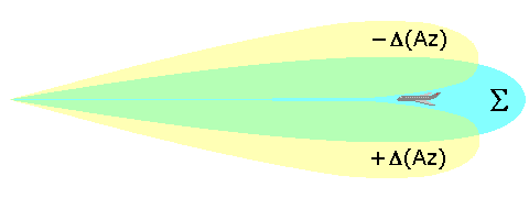
It is possible to jam a lobe switching radar with relative ease if one knows the basic operating frequencies of the radar. In the case of a lobe switching set that switches lobes 30 times a second, a jammer can be constructed to send out a weak signal on the same frequency that also varies 30 times a second, but only sends out a signal when the radar's lobe is pointed away from the aircraft – which is easily found by looking for a low point in the received signal. At the receiver end the two signals are mixed, and the additional signal from the aircraft's jammer "smooths out" the strong/weak signal that would otherwise be seen. This denies the radar angle information, and can make anything but gross angle tracking difficult.
One way to avoid this problem is used in the LORO radar, short for Lobe On Receive Only, which uses one set of antenna elements to send a non-lobed signal, and two additional sets for lobing on reception. Operation is basically identical to a normal lobing radar, but it denies any information about the lobing to the target aircraft, for the cost of some additional antenna elements (or more commonly, a second antenna). Unsynchronized "blocks" of signal can be used to jam LORO radars, although it is not as effective as against a "normal" lobing system and generally makes the operator's job difficult, as opposed to impossible.
External links
- This lobe switching concept was used in the so-called Flimmerschalter in the German Lichtenstein radar during World War II. (see Radar tutorial)