Gridded ion thruster
The gridded ion thruster is a common design for ion thrusters, a highly efficient low-thrust spacecraft propulsion running on electrical power. These designs use high-voltage grid electrodes to accelerate ions with electrostatic forces.
History
The ion engine was first demonstrated by German-born NASA scientist Ernst Stuhlinger,[1] and developed in practical form by Harold R. Kaufman at NASA Lewis (now Glenn) Research Center from 1957 to the early 1960s.
The use of ion propulsion systems were first demonstrated in space by the NASA Lewis "Space Electric Rocket Test" (SERT) I and II.[2] These thrusters used mercury as the reaction mass. The first was SERT-1, launched July 20, 1964, which successfully proved that the technology operated as predicted in space. The second test, SERT-II, launched on February 3, 1970,[3][4] verified the operation of two mercury ion engines for thousands of running hours.[5] Despite the demonstration in the 1960s and 70s, though, they were rarely used before the late 1990s.
NASA Glenn continued to develop electrostatic gridded ion thrusters through the 1980s, developing the NASA Solar Technology Application Readiness (NSTAR) engine, that was used successfully on the Deep Space 1 probe, the first mission to fly an interplanetary trajectory using electric propulsion as the primary propulsion. It is currently flying the Dawn asteroid mission. Hughes Aircraft Company (now L-3 ETI) has developed the XIPS (Xenon Ion Propulsion System) for performing station keeping on its geosynchronous satellites (more than 100 engines flying). NASA is currently working on a 20-50 kW electrostatic ion thruster called HiPEP which will have higher efficiency, specific impulse, and a longer lifetime than NSTAR. Aerojet has recently completed testing of a prototype NEXT ion thruster.[6] At Giessen University and EADS the radio-frequency ion thrusters RIT were developed starting in the 1970s. RIT-10 engines are flying on ARTEMIS. Qinetiq (UK) has developed the T5 and T6 engines (Kaufman type), flying the GOCE mission (T5) and is baselined for BepiColombo mission (T6). In Japan, microwave engines µ10 flew on the Hayabusa mission.
Method of operation
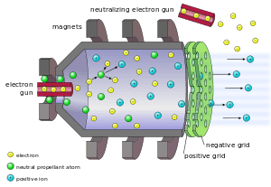
- Propellant atoms are injected into the discharge chamber and are ionized by electron bombardment, forming a plasma. There are several ways of producing the energetic electrons for the discharge: (1) The electrons are emitted from a hollow cathode and are accelerated on their way to the anode (Kaufman type ion thruster). (2) The electrons can be accelerated by the oscillating electric field induced by an alternating magnetic field of a coil, which results in a self-sustaining discharge and omits any cathode (radiofrequency ion thruster). (3) Microwave heating
- The positively charged ions move towards the extraction system (2 or 3 multi-aperture grids) of the chamber due to diffusion. Once ions enter the plasma sheath at a grid hole they will be accelerated by the potential difference between the first (screen) and the second (accelerator) grid of the extraction system. The ions are ion-optically focused by the rather large electric field to pass through the extraction holes. The final ion energy is determined by the potential of the plasma (the plasma potential is a few volts larger than the screen grid voltage).
- The negative voltage of the accelerator grid prevents electrons of the beam plasma outside the thruster from streaming back to the discharge plasma. Electron backstreaming occurs if the potential within the grid is not sufficiently negative, this can mark the end-of-life of the ion thruster. By increasing the negative voltage electron backstreaming can be avoided.
- The expelled ions propel the spacecraft in the opposite direction according to Newton's 3rd law.
- Electrons are emitted from a separate cathode placed near the ion beam, called the neutralizer, towards the ion beam to ensure that equal amounts of positive and negative charge are ejected. Neutralizing is needed to prevent the spacecraft from gaining a net negative charge.
Performance
The ion optics are constantly bombarded by a small amount of secondary ions and erode or wear away, thus reducing engine efficiency and life. Ion engines need to be able to run efficiently and continuously for years. Several techniques were used to reduce erosion; most notable was switching to a different propellant. Mercury or caesium atoms were used as propellants during tests in the 1960s and 1970s, but these propellants adhered to, and eroded the grids. Xenon atoms, on the other hand, are far less corrosive, and became the propellant of choice for virtually all ion thruster types. NASA has demonstrated continuous operation of NSTAR engines for over 16,000 hours (1.8 years), and tests are still ongoing for double this lifetime. Electrostatic ion thrusters have also achieved a specific impulse of 30–100 kN·s/kg, better than most other ion thruster types. Electrostatic ion thrusters have accelerated ions to speeds reaching 100 km/s.
In January 2006, the European Space Agency, together with the Australian National University, have announced successful testing of an improved electrostatic ion engine, the Dual-Stage 4-Grid (DS4G), that showed exhaust speeds of 210 km/s, reportedly four times higher than previously achieved, allowing for a specific impulse which is four times higher. Conventional electrostatic ion thrusters possess only two grids, one high voltage and one low voltage, which perform both the ion extraction and acceleration functions. However, when the charge differential between these grids reaches around 5 kV, some of the particles extracted from the chamber collide with the low voltage grid, eroding it and compromising the engine's longevity. This limitation is successfully bypassed when two pairs of grids are used. The first pair operates at high voltage, possessing a voltage differential of around 3 kV between them; this grid pair is responsible for extracting the charged propellant particles from the gas chamber. The second pair, operating at low voltage, provides the electrical field that accelerates the particles outwards, creating thrust. Other advantages to the new engine include a more compact design, allowing it to be scaled up to higher thrusts, and a narrower, less divergent exhaust plume of 3 degrees, which is reportedly five times narrower than previously achieved. This reduces the propellant needed to correct the orientation of the spacecraft due to small uncertainties in the thrust vector direction.[7]
Variants
The largest difference in the many electrostatic ion thrusters is the method of ionizing the propellant atoms - electron bombardment (NSTAR, NEXT, T5, T6), radiofrequency (rf) excitation (RIT 10, RIT 22, µN-RIT), microwave excitation (µ10, µ20). Related to this is the need of a cathode and required effort for the power supplies. Kaufman type engines require at least supplies to the cathode, anode and chamber, whereas the rf and microwave types require an additional rf generator, but no anode and cathode supplies.
In the extraction grid systems minor differences occur in the grid geometry and the materials used, which may have implications for the grid system lifetime.
See also
References
- ↑ Ernst Stuhlinger, Ion Propulsion for Space Flight (McGraw-Hill, New York, 1964).
- ↑ J. S. Sovey, V. K. Rawlin, and M. J. Patterson, "Ion Propulsion Development Projects in U. S.: Space Electric Rocket Test 1 to Deep Space 1", Journal of Propulsion and Power, Vol. 17, No. 3, May–June 2001, pp. 517-526.
- ↑ NASA Glenn, "SPACE ELECTRIC ROCKET TEST II (SERT II) (Accessed July 1, 2010)
- ↑ SERT page at Astronautix (Accessed July 1, 2010)
- ↑ Space Electric Rocket Test
- ↑ Aerojet Successfully Completes Manufacturing and System Integration Milestones for NASA's NEXT Ion Engine Development Program Archived May 30, 2006, at the Wayback Machine.
- ↑ ESA Portal - ESA and ANU make space propulsion breakthrough
External links
- Aerojet (Redmond, Washington USA) - Gridded Ion Thruster Vendor
- NSTAR ion engine
- Technologies to Improve Ion Propulsion System (PDF)
- Electric Thruster Systems (PDF)
- HiPEP
- ESA And ANU Make Space Propulsion Breakthrough
| Chemical rockets |
| ||||||||||||||
|---|---|---|---|---|---|---|---|---|---|---|---|---|---|---|---|
| Electrical thrusters |
| ||||||||||||||
| Nuclear propulsion |
| ||||||||||||||
| Other | |||||||||||||||