Field flow fractionation
Field-flow fractionation, abbreviated FFF, is a separation technique where a field is applied to a fluid suspension or solution pumped through a long and narrow channel, perpendicular to the direction of flow, to cause separation of the particles present in the fluid, depending on their differing "mobilities" under the force exerted by the field. It was invented and first reported by J. Calvin Giddings.[1] The method of FFF is unique to other separation techniques due to the fact that it can separate materials over a wide colloidal size range while maintaining high resolution. Although FFF is an extremely versatile technique, there is no "one size fits all" method for all applications.
.jpg)
In field-flow fractionation the field can be asymmetrical flow through a semi-permeable membrane, gravitational, centrifugal, thermal-gradient, electrical, magnetic etc. In all cases, the separation mechanism is born from differences in particle mobility (electrophoretic, when the field is a DC electric field causing a transverse electric current flow) under the forces of the field, in equilibrium with the forces of diffusion: an often-parabolic laminar-flow-velocity profile in the channel determines the velocity of a particular particle, based on its equilibrium position from the wall of the channel. The ratio of the velocity of a species of particle to the average velocity of the fluid is called the retention ratio.
Fundamental principles
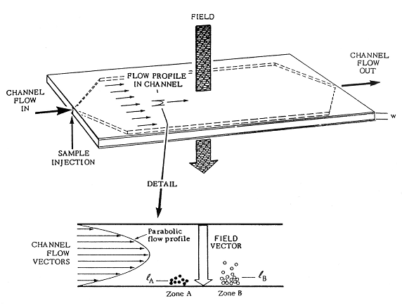
Field flow fractionation is based on laminar flow of particles in a solution. These sample components will change levels and speed based on their size/mass. Since these components will be travelling at different speeds, separation occurs. A simplified explanation of the setup is as follows. The sample separation occurs in a thin, ribbon-like, channel in which there is an inlet flow and a perpendicular field flow. The inlet flow is where the carrier liquid is pumped into the channel and it creates a parabolic flow profile and it propels the sample towards the outlet of the channel.
Relating force (F) to retention time (TR)
The relationship between the separative force field and retention time can be illustrated from first principles. Consider two particle populations within the FFF channel. The cross field drives both particle clouds towards the bottom "accumulation" wall. Opposing this force field is the particles natural diffusion, or Brownian motion, which produces a counter acting motion. When these two transport process reach equilibrium the particle concentration c approaches the exponential function of elevation x above the accumulation wall as illustrated in equation 1.

l represents the characteristic elevation of the particle cloud. This relates to the height that the particle group can reach within the channel and only when the value for l is different for either group will separation occur. The l of each component can be related to the force applied on each individual particle.

Where k is the Boltzmann constant, T is absolute pressure and F is the force exerted on a single particle by the cross flow. This shows how the characteristic elevation value is inversely dependent to the Force applied. Therefore, F governs the separation process. Hence, by varying the field strength the separation can be controlled to achieve optimal levels. The velocity V of a cloud of molecules is simply the average velocity of an exponential distribution embedded in a parabolic flow profile. Retention time, tr can be written as:

Where L is the channel length. Subsequently, the retention time can be written as:
tr/to = w/6l ⌊coth w/2l- 2l/w⌋−1
Where to is the void time (emergence of a non-retained tracer) and w is the sample thickness. Substituting in kT/F in place of l illustrates the retention time with respect to the cross force applied.
tr/to = Fw/6kT ⌊coth Fw/2kT- 2kT/Fw⌋−1
For an efficient operation the channel thickness value w far exceeds l. When this is the case the term in the brackets approaches unity. Therefore, equation 5 can be approximated as:
tr/to = w/6l = Fw/6kT
Thus tr is roughly proportional to F. The separation of particle bands X and Y, represented by the finite increment ∆tr in their retention times, is achieved only if the force increment ∆F between them is sufficient. A differential in force of only 10–16 N is required for this to be the case. The magnitude of F and ∆F depend on particle properties, field strength and the type of field. This allows for variations and specialisations for the technique. From this basic principle many forms of FFF have evolved varying by the nature of the separative force applied and the range in molecule size to which they are targeted.
Fractogram

A graph of a detection signal vs. time, derived from an FFF process, in which various substances present in a fluid get separated based on their flow velocities under some applied external field, such as an flow, centrifugal, thermal or electric field.
Often these substances are various particles initially suspended in a small volume of a liquid buffer and pushed along a fractionation channel by more of the pure buffer. The varying velocities of a particular species of particles may be due to its size, its mass, and/or its distance from the walls of a channel with non-uniform flow-velocity. The presence of different species in a sample can thus be identified through detection of a common property at some distance down the long channel, and by the resulting fractogram indicating the presence of the various species by peaks, due to the different times of arrival characteristic of each species and its physical and chemical properties.
In an electrical FFF, an electric field controls the velocity by controlling the lateral position of either a charged (having electrophoretic mobility) or polarized (being levitated in a non-uniform field) species in a capillary channel with a hydrodynamically parabolic flow-velocity profile, meaning that the velocity of the pumped fluid is highest midway between the walls of the channel and it monotonically decays to a minimum of zero at the wall surface.[2]
Forms of FFF
Most techniques available today are advances on those originally created by Prof. Giddings nearly 4 decades ago.
Flow FFF
Of these techniques Flow FFF was the first to be offered commercially. Flow FFF separates particles based on size, independent of density and can measure macromolecules in the range of 1 nm to 1 µm. In this respect it is the most sensitive FFF technique available. The cross flow in Flow FFF enters through a porous frit at the top of the channel, exiting through a semi-permeable membrane outlet frit on the accumulation wall (i.e. the bottom wall).
Hollow fiber flow FFF
Hollow fiber flow FFF (HF5) has been pioneered by H.L. Lee, J.F.G. Reis and E. N. Lightfoot.[3] HF5 has been applied towards the analysis of lattices and other macromolecules. HF5 was the first form of flow FFF (1974) to be developed. Flat membranes soon outperformed hollow fibers and forced HF5 into obscurity. One of the drawbacks of HF5 is the availability of the membranes with uniform pore sizes. There are different kinds of ceramic and polymeric hollow fiber membranes used in practice.
Asymmetric flow FFF (AF4)
Asymmetric Flow FFF (AF4), on the other hand, has only one semi-permeable membrane on the bottom wall of the channel. The cross flow is, therefore, created by the carrier liquid exiting the bottom of the channel. This offers an extremely gentle separation and an “ultra-broad” separation range. High Temperature Asymmetric Flow Field-Flow Fractionation is the most advanced technology for the separation of high and ultra-high molar mass polymers, macromolecules and nanoparticles in the size range.
Thermal FFF
Thermal FFF, as the name suggests, establishes a separation force by applying a temperature gradient to the channel. The top channel wall is heated and the bottom wall is cooled driving polymers and particles towards the cold wall by thermal diffusion. Thermal FFF was developed as a technique for separating synthetic polymers in organic solvents. Thermal FFF is unique amongst FFF techniques in that it can separate macromolecules by both molar mass and chemical composition, allowing for the separation of polymer fractions with the same molecular weight. Today this technique is ideally suited for the characterization of polymers, gels and nanoparticles.
Split flow thin-cell fractionation (SPLITT)
Split flow thin-cell fractionation (SPLITT) is a special preparative FFF technique, using gravity for separation of µm-sized particles on a continuous basis. SPLITT is performed by pumping the sample containing liquid into the top inlet at the start of the channel, whilst simultaneously pumping a carrier liquid into the bottom inlet. By controlling the flow rate ratios of the two inlet streams and two outlet streams, the separation can be controlled and the sample separated into two distinct sized fractions. The use of gravity alone as the separating force makes SPLITT the least sensitive FFF technique, limited to particles above 1 µm.
Centrifugal FFF
With further developments in sedimentation FFF, this has led to the development of a new technique, centrifugal FFF, wherein the separation field is supplied via a centrifugal force. The channel takes the form of a ring, which spins at 4900 rpm. The flow and sample are pumped into the chamber and the mixture is centrifuged, allowing the operator to resolve the particles by size and density. The advantage of centrifugal FFF lies in the broad range of samples and high resolution that can be achieved by varying the speed and force applied.
The unique advantage presented by centrifugal FFF comes from the techniques capability for high resolution. The first commercial centrifugal FFF instrument was introduced by Postnova Analytics is the CF2000, incorporating the unique feature of separating particles by dynamic diffusion on the basis of both particle size and density. This allows for the separation of particles with only a 5% difference in size. Centrifugal FFF has the advantage that molecules can be separated by particle density, rather than just particle size. In this instance, two identically sized gold and silver nanoparticles can be separated into two peaks, according to differences in density in the gold and silver nanoparticles, separated with the Centrifugal FFF Postnova CF2000 instrument with the detection by Dynamic Light Scattering (DLS).
In AF4 separations, the ratio of mass to time is 1:1. With the addition of the third parameter of density to centrifugal fractionation, this produces a ratio more akin to mass:time to the power of three. This results in a significantly larger distinction between peaks and result in a greatly improved resolution. This can be particularly useful for novel products, such as composite materials and coated polymers containing nanoparticles, particles which may not vary in size but do vary in density. In this way two identically sized particles can still be separated into two peaks, providing that the density is different.
References
- ↑ Giddings, JC, FJ Yang, and MN Myers. "Flow Field-Flow Fractionation: a versatile new separation method.” Science 193.4259 (1976): 1244–1245.
- ↑ Madou, Marc (2001). Fundamentals of Microfabrication. US: CRC. pp. 565–571. ISBN 0-8493-0826-7.
- ↑ H.L. Lee, J.F.G. Reis and E. N. Lightfoot, AIChE Journal edition 20, 1974, page 776 entitled Single-phase chromatography: Solute retardation by ultrafiltration and electrophoresis
External links
- American Laboratory: Field-Flow Fractionation Supporting Consumer Safety
- Diagram
- Example
- Postnova Analytics GmbH
- Wyatt Technology GmbH
- Wyatt Technology Europe GmbH
- FFF-Platform