Computer case screws

Computer case screws are the hardware used to secure parts of a PC to the case. Although there are numerous manufacturers of computer cases, they have generally used three thread sizes. The Unified Thread Standard (UTS) originates from the United States while the ISO metric screw thread is standardized worldwide. In turn, these thread standards define preferred size combinations that are based on generic units—some on the inch and others on the millimeter.
The #6-32 UNC screws are often found on hard disk drives and the case's body to secure the covers. The M3 threaded holes are often found on optical disc drives and floppy drives. Motherboards and other circuit boards often use a #6-32 UNC standoff. #4-40 UNC thumb screws are often found on the ends of DVI, VGA, and older Serial and Parallel cables.
More modern cases from certain manufacturers (Dell, Gateway) and enthusiast cases will lack screws altogether, instead utilizing a tool-less design.
#6-32 UNC screw
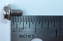
The #6-32 UNC is a UTS screw specifying a major thread diameter of #6 which is defined as 0.1380 inches (3.51 mm); and 32 tpi (threads per inch) which equates to a thread pitch of 0.031250 inches (0.7938 mm). The optional UNC specification indicates the standard coarse thread is used which is defined for #6 screws as 32 tpi rendering 'UNC' redundant, however it may be seen when other specifications such as plating or other treatments are also specified. It is by far the most common screw found inside computer cases.[1] It commonly appears in lengths of 3/16 in (0.1875 inches (4.76 mm)) and 1/4 in (0.25 inches (6.4 mm)) or less often 5/16 in (0.3125 inches (7.94 mm)). Non-standard metricized lengths such as 5 millimetres (0.20 in) are also sometimes encountered. Nearly every brand new computer case comes with a bag of these. They are commonly used for the following purposes, however there are many exceptions:
- To secure a power supply to the case
- To secure a 3.5 in hard disk drive to the case
- To hold an expansion card in place by its metal slot cover
- To fasten case components to one another
- Usually, a #6-32 UNC screw holds the main cover on the case.
They are almost always provided with a #2 Phillips drive. Sometimes a Torx drive is used instead. Both Phillips and Torx patterns may also be combined with a slot for a flat-blade screwdriver. Usually they are provided with a 1/4 in (0.25 inches (6.4 mm)) flanged hex head. Non-standard metricized 5.5 millimetres (0.22 in) flanged hex heads can also be encountered. Also common are pan head screws - a low disk with a chamfered outer edge. Because they are used in places where high torque is not required and easy removal and replacement may be desirable (such as on the side panels of the PC case), they are frequently available as thumbscrews with larger, knurled heads that can be removed with one's fingers or tools.
M3 screw
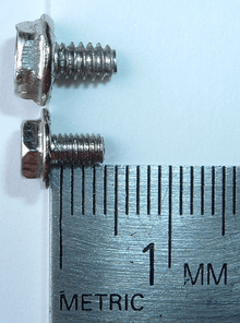
The M3 is a metric screw specifying a nominal diameter of 3 millimetres (0.12 in); and standard coarse thread pitch defined as 0.5 millimetres (0.020 in). The M3 is the second most common screw found in PCs.[1] It commonly appears in many lengths from 1-20mm. Nearly every brand new computer case comes with a bag of these. They are commonly used for the following purposes,[2] however there are many exceptions:
- securing optical disc drives
- 2.5-inch hard disk drives (HDDs)
- solid-state drives (SSDs)
- floppy drives
M3 screws typically accept a #1 Phillips screwdriver tip.
Motherboard standoff
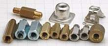
Most cases use threaded brass standoffs (Jack Screw Standoffs) for attaching the motherboard to the case chassis. Sometimes threaded or snap-lock plastic standoffs are used, which are less secure, but equally useful in a stationary computer. The standoff provides a margin of space between the motherboard and the case to keep the multiple solder points below from grounding and short-circuiting.
Usually the standoff has a #6-32 UNC male thread on one end which screws into a threaded hole in the case or motherboard backplate, and a #6-32 UNC female thread in the other end which accepts a screw to retain the motherboard. Less often, the standoff has a female thread in both ends and a second screw is used to attach it to the case. Some standoffs use the M3 female thread (which faces the motherboard) instead of #6-32 UNC, and on a rare occasion a mixture of types can be used in the same case.
Version 2.1 of the ATX specification states that the length of standoffs needs to be at least 0.25 inches (6.4 mm), with their cross sections fitting within 0.40 by 0.40 inches (10 mm × 10 mm) square areas centered around each mounting hole on ATX motherboards.[3]
#4-40 UNC thumbscrews
Pairs of #4-40 UNC thumbscrews are used to fasten certain connectors to hardware ports. The screws are typically located on either side of D-subminiature connectors such as on VGA, serial, parallel, and legacy game controller ports. They are also more recently used on DVI connectors. The typical length for a #4-40 screw used in PCs is 3/16 in (0.1875 inches (4.76 mm)).
Material
Steel is by far the most common material used, frequently with a plated or anodized finish. Other materials including brass, aluminum, nylon, and various plastics are also used for applications with particular physical or aesthetic requirements.
Comparison
The #6-32 UNC is a thicker screw with a more coarse thread. This makes it more suitable for fastening larger parts and thicker materials requiring increased holding strength. It's larger size and coarse thread make it easier to work with during assembly, with less risk of cross threading. The integrated flange provides greater holding strength with less risk of pull through. The hex head makes it easier to work with during assembly with powered torque screwdrivers.
The M3 is a thinner screw with a finer thread than the #6-32 UNC. This makes it more suitable for fastening into smaller parts and thinner materials requiring good strength in a limited space. It's size and fine thread make it appropriate for applications where a #6-32 UNC would be excessively bulky without providing any other benefits versus the smaller M3.
Gallery
-

Close-up of a #6-32 UNC screw with a flanged hex/Phillips head, commonly provided in PC cases.
-
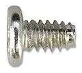
Close-up of a #6-32 UNC screw with a Phillips pan head, commonly provided in PC cases.
-

Thumbscrews from an ATX PC case
References
- 1 2 Rutter, Daniel Dan's Data - Letters 53, "Screwed", 2006-02-26
- ↑ "2.5-inch Hard Disk Drives Installation Guide" (PDF). HGST. January 30, 2007. Archived from the original (PDF) on December 24, 2012. Retrieved November 16, 2014.
- ↑ "ATX Specification, Version 2.1: Section 3.4.2 Secondary (Bottom/Solder) Side Height Constraints" (PDF). formfactors.org. 2012-08-18. p. 18. Retrieved 2014-12-22.
External links
- McDonough, Andy The 11 Tools Every System Builder Should Own retrieved Nov 2, 2014 from crn.com
- Torres, Gabriel Everything You Need To Know About The Screws Used on The PC retrieved Jun 20, 2016 from hardwaresecrets.com