Bearing pressure
| Continuum mechanics | ||||
|---|---|---|---|---|
 | ||||
|
Laws
|
||||
Bearing pressure is a particular case of contact mechanics often occurring in cases where a convex surface (male cylinder or sphere) contacts a concave surface (female cylinder or sphere: bore or hemispherical cup). Excessive contact pressure can lead to a typical bearing failure such as a plastic deformation similar to peening. This problem is also referred to as bearing resistance.[1]
Hypotheses
A contact between a male part (convex) and a female part (concave) is considered when the radii of curvature are close to one another. There is no tightening and the joint slides with no friction therefore, the contact forces are normal to the tangent of the contact surface.
Moreover, bearing pressure is restricted to the case where the charge can be described by a radial force pointing towards the center of the joint.
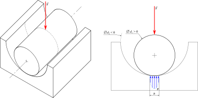
Case of a cylinder-cylinder contact
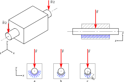
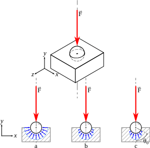
In the case of a revolute joint or of a hinge joint, there is a contact between a male cylinder and a female cylinder. The complexity depends on the situation, and three cases are distinguished:
- the clearance is negligible:
- a) the parts are rigid bodies,
- b) the parts are elastic bodies;
- c) the clearance cannot be ignored and the parts are elastic bodies.
By "negligible clearance", H7/g6 fit is typically meant.
The axes of the cylinders are along the z-axis, and two external forces apply to the male cylinder:
- a force along the y-axis, the load;
- the action of the bore (contact pressure).

The main concern is the contact pressure with the bore, which is uniformly distributed along the z-axis.
Notation:
- D is the nominal diameter of both male and female cylinders;[2]
- L the guiding length.
Negligible clearance and rigid bodies
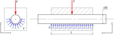
In this first modeling, the pressure is uniform. It is equal to[3] · [4] · :[5]
- .

Negligible clearance and elastic bodies

If it is considered that the parts deform elastically, then the contact pressure is no longer uniform and transforms to a sinusoidal repartition[6] · :[7]
- P(θ) = Pmax⋅cos θ
with
- .

This is a particular case of the following section (θ0 = π/2).
The maximum pressure is 4/π ≃ 1.27 times bigger than the case of uniform pressure.
Clearance and elastic bodies
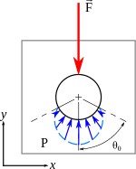
In cases where the clearance can not be neglected, the contact between the male part is no longer the whole half-cylinder surface but is limited to a 2θ0 angle. The pressure follows Hooke's law:[8]
- P(θ) = K⋅δα(θ)
where
- K is a positive real number that represents the rigidity of the materials;
- δ(θ) is the radial displacement of the contact point at the angle θ;
- α is a coefficient that represents the behaviour of the material:
- α = 1 for metals (purely elastic behaviour),
- α > 1 for polymers (viscoelastic or viscoplastic behaviour).
The pressure varies as:
- A⋅cos θ - B
where A and B are positive real number. The maximum pressure is:

the angle θ0 is in radians.
The rigidity coefficient K and the half contact angle θ0 can not be derived from the theory. They must be measured. For a given system — given diameters and materials —, thus for given K and clearance j values, it is possible to obtain a curve θ0 = ƒ(F/(DL)).
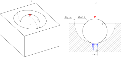
Case of a sphere-sphere contact
A sphere-sphere contact corresponds to a spherical joint (socket/ball), such as a ball jointed cylinder saddle. It can also describe the situation of bearing balls.
Case of uniform pressure
The case is similar as above: when the parts are considered as rigid bodies and the clearance can be neglected, then the pressure is supposed to be uniform. It can also be calculated considering the projected area[3] · [9] · :[10]
- .

Case of a sinusoidal repartition of pressure
As in the case of cylinder-cylinder contact, when the parts are modeled as elastic bodies with a negligible clearance, then the pressure can be modeled with a snusoidal repartition[6] · :[11]
- P(θ, φ) = Pmax⋅cos θ
with
- .

Hertz contact stress
When the clearance can not be neglected, it is then necessary to know the value of the half contact angle θ0 , which can not be determined in a simple way and must be measured. When this value is not available, the Hertz contact theory can be used.
The Hertz theory is normally only valid when the surfaces can not conform, or in other terms, can not fit each other by elastic deformation; one surface must be convex, the other one must be also convex or plane. This is not the case here, so the results must be considered with great care. The approximation is only valid when the inner radius of the container R1 is far greater than the outer radius of the content R2, in which case the surface container is then seen as flat by the content. However, in all cases, the pressure that is calculated with the Hertz theory is greater than the actual pressure (because the contact surface of the model is smaller than the real contact surface), which affords designers with a safety margin for their design.
In this theory, the radius of the female part (concave) is negative.[12]
A relative diameter of curvature is defined:

where d1 is the diameter of the female part (negative) and d2 is the diameter of the male part (positive). An equivalent module of elasticity is also defined:

where νi is the Poisson's ratio of the material of the part i and Ei its Young's modulus.
For a cylinder-cylinder contact, the width of the contact surface is:

and the maximal pressure is in the middle:
- .

In case of a sphere-sphere contact, the contact surface is a disk whose radius is:

and the maximal pressure is in the middle:
- .
![{\displaystyle P_{\max }={\frac {3F}{\pi a^{2}}}={\frac {4}{\pi }}{\sqrt[{3}]{3F\left({\frac {E^{*}}{d^{*}}}\right)^{2}}}}](../I/m/e38b81cdda848d4976e25464a01ff0713d3060f7.svg)
Applications
Bolt used as a stop
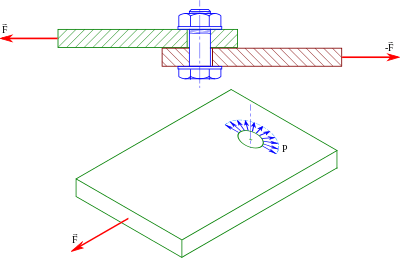
In a bolted connection, the role of the bolts is normally to press one parts on the other; the adherence (friction) is opposed to the tangent forces and prevents the parts from sliding apart. In some cases however, the adherence is not sufficient. The bolts then play the role of stops: the screws endure shear stress whereas the hole endure bearing pressure.
In good design practice, the threaded part of the screw should be small and only the smooth part should be in contact with the plates; in the case of a shoulder screw, the clearance between the screw and the hole is very small ( a case of rigid bodies with negligible clearance). If the acceptable pressure limit Plim of the material is known, the thickness t of the part and the diameter d of the screw, then the maximum acceptable tangent force for one bolt Fb, Rd (design bearing resistance per bolt) is:
- Fb, Rd = Plim × d × t.
In this case, the acceptable pressure limit is calculated from the ultimate tensile stress fu and factors of safety, according to the Eurocode 3 standard[1] · .[13] In the case of two plates with a single overlap and one row of bolts, the formula is:
- Plim = 1.5 × fu/γM2
where
- γM2 = 1.25: partial safety factor.
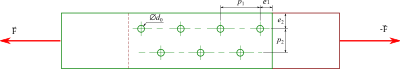
In more complex situations, the formula is:
- Plim = k1 × α × fu/γM2
where
- k1 and α are factors that take into account other failure modes than the bearing pressure overload; k1 take into account the effects that are perpendicular to the tangent force, and α the effects along the force;
- k1 = min{2.8e2/d0 ; 2.5} for end bolts,
k1 = min{1.4p2/d0 ; 2.5} for inner bolts,- e2: edge distance from the centre of a fastener hole to the adjacent edge of the part, measured at right angles to the direction of load transfer,
- p2: spacing measured perpendicular to the load transfer direction between adjacent lines of
fasteners,
- d0: diameter of the passthrough hole;
- α = min{e1/3d0 ; p1/3d0 - 1/4 ; fub/fu ; 1}, with
- e1: end distance from the center of a fastener hole to the adjacent end of the part, measured in the direction of load transfer,
- p1: spacing between centers of fasteners in the direction of load transfer,
- fub: specified ultimate tensile strength of the bolt.
| Steel grades (EN standard) | S235 | S275 | S355 |
|---|---|---|---|
| Ultimate tensile stress fu (MPa) |
360 | 430 | 510 |
When the parts are in wood, the acceptable limit pressure is about 4 to 8.5 MP.[14]
Plain bearing
In plain bearings, the shaft is usually in contact with a bushing (sleeve or flanged) to reduce friction. When the rotation is slow and the load is radial, the model of uniform pressure can be used (small deformations and clearance).
The product of the bearing pressure times the circumferential sliding speed, called load factor PV, is an estimation of the resistance capacity of the material against the frictional heating[15] · [16] · .[17]
| Type of bushing Maximal circumferential sliding speed |
Acceptable bearing pressure (MPa) |
|---|---|
| Self-lubricating bushels 7 to 8 m/s 13 m/s for graphite |
graphite: 5 lead bronze: 20 to 30 tin bronze: 7 to 35 |
| Composite bushing, Glacier 2 to 3 m/s |
acetal: 70 PTFE: 50 |
| Polymer bushing 2 to 3 m/s | 7 to 10 |
References
- 1 2 3 EN 1993-1-8:2005 Eurocode 3: Design of steel structures - Part 1-8: Design of joints
- ↑ due to the clearance, the diameter of the bore is bigger than the diameter of the male cylinder; however, we suppose that the diameters are close to each othert
- 1 2 (SG 2003, p. 139)
- ↑ (GCM 2000, p. 177)
- ↑ (Aublin 1992, pp. 108, 136)
- 1 2 (SG 2003, p. 140)
- ↑ (Aublin 1992, pp. 120–122, 136–137)
- ↑ (Aublin 1992, pp. 120–122, 137–138)
- ↑ (GCM 2000, pp. 110–111)
- ↑ (Aublin 1992, pp. 108, 144–145)
- ↑ (Aublin 1992, pp. 120–122, 145–150)
- ↑ (Fanchon 2001, pp. 467–471)
- 1 2 Seinturier, Francine. "C-viii Assemblages boulonnés". Construction métallique 2 (PDF) (in French). IUT Grenoble I.
- ↑ MB (April 2007). "Assemblages". Wiki de l'Unité Construction de Gramme (in French). Retrieved 2015-11-25.
- ↑ (Fanchon 2011, p. 255)
- ↑ (Chevalier 2004, p. 258)
- ↑ (GCM 2000, pp. 113–116, 176–181)
- ↑ L.P. Pierre et Marie Curie, Aulnoye. "Paliers lisses ou coussinets". Construction mécanique (PDF) (in French). Université de Toulon.
Bibliography
- [Aublin 1992] Aublin, Michel; Boncompain, René; Boulaton, Michel; Caron, Daniel; Jeay, Émile; Lacage, Bernard; Réa, Jacky (1992). Systèmes mécaniques : théorie et dimensionnement (in French). Dunod. pp. 108–157. ISBN 2-10-001051-4.
- [Chevalier 2004] Chevalier, André (2004). Guide du dessinateur industriel (in French). Hachette technique. p. 258. ISBN 978-2-01-168831-6.
- [Fanchon 2001] Fanchon, Jean-Louis (2001). Guide de mécanique : sciences et technologies industrielles (in French). Nathan. pp. 467–471. ISBN 978-2-09-178965-1.
- [Fanchon 2011] Fanchon, Jean-Louis (2011). "Calcul des coussinets (régime non hydrodynamique)". Guide des sciences et technologies industrielles (in French). Afnor/Nathan. pp. 255–256. ISBN 978-2-09-161590-5.
- [GCM 2000] Texeido, C.; Jouanne, J.-C.; Bauwe, B.; Chambraud, P.; Ignatio, G.; Guérin, C. (2000). Guide de construction mécanique (in French). Delagrave. pp. 110–116, 176–180. ISBN 978-2-206-08224-0.
- [SG 2003] Spenlé, D.; Gourhant, R. (2003). Guide du calcul en mécanique : maîtriser la performance des systèmes industriels (in French). Hachette technique. pp. 139–140. ISBN 2-01-16-8835-3.